Film scanning device

A scanning device and negative film technology, which is applied in the direction of scanning details, TVs, electrical components, etc. in the TV system, and can solve the problem of large scanner volume

Inactive Publication Date: 2011-05-25
MUSTEK SYSTEMS
View PDF0 Cites 0 Cited by
  • Summary
  • Abstract
  • Description
  • Claims
  • Application Information

AI Technical Summary

Problems solved by technology

[0005] The object of the present invention is to provide a negative film scanner that uses a mirror to change the light path and direction of the film imaging to reduce the size, so as to solve the above-mentioned shortcomings of the general negative film scanner that are relatively large

Method used


Image

  • Film scanning device
  • Film scanning device
  • Film scanning device

Examples


Embodiment Construction

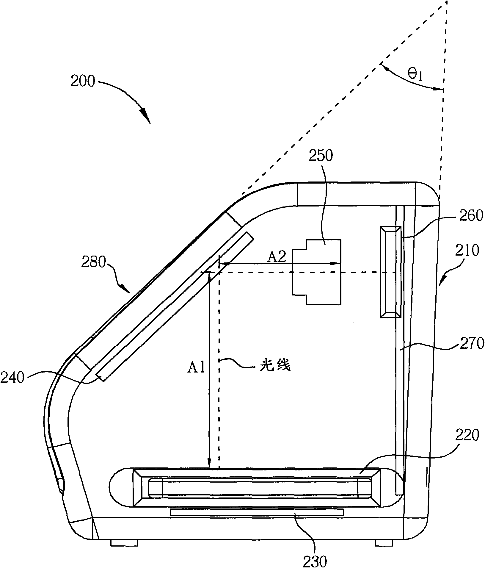
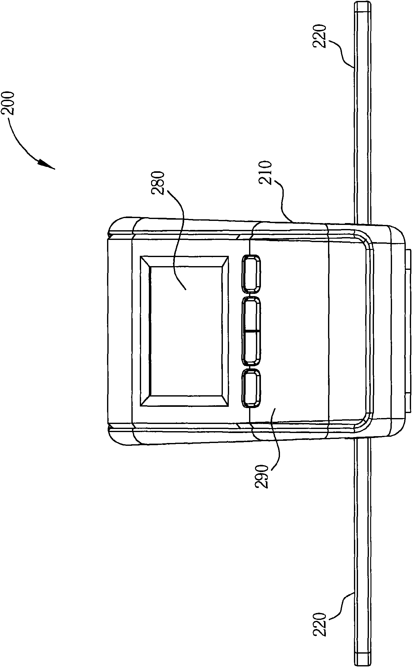
[0033] see Figure 2 to Figure 7 , which is a schematic six-sided schematic diagram of a film scanner 200 provided according to a first embodiment of the present invention, and figure 2 It is shown in a perspective view in order to explain in detail the various components included inside the film scanner 200, and Figure 8 It is a simplified perspective view of the film scanner 200 . Such as Figure 2 to Figure 8 As shown, the film scanner 200 includes a housing 210, a film insertion seat 220, a backlight module 230, a mirror 240, a sensing module 250, a secure digital memory card holder 260, an image processing module 270, a A display panel 280, and a control panel 290, wherein the sensing module 250 is disposed on a first side of the housing 210 and near the top of the housing 210, the mirror 240 is disposed on a second side of the housing 210, and Both the first side and the second side form an included angle in the extending direction, for example figure 2 θ 1 . Th...


PUM


Abstract

The invention provides a film scanning device. The film scanning device comprises a shell, a film imbedding seat, a backlight module, an induction module and an image processing module and is characterized by also comprising a mirror surface, wherein the film imbedding seat is arranged in the shell; the backlight module is arranged in the shell for projecting light to a film which is loaded on the film imbedding seat to provide light required for film development; the induction module is arranged corresponding to a first side face in the shell; the image processing module is used for converting an image which is received by the induction module into a digital image; and the mirror surface is arranged on a second side face in the shell for reflecting the light which is projected to the film by the backlight module to the induction module, so that the induction module collects the light which is projected to the film by the backlight module and receives the image stored by the film.

Description

technical field [0001] The invention relates to a film scanning device, in particular to a film scanning device which changes the direction and path of light transmission through a reflector to reduce the volume. Background technique [0002] Generally, traditional cameras use photosensitive film including positive film or negative film as the negative film for recording images. When users want to view the photographed negative film, in addition to directly developing the negative film to a blank photo by chemical processing method for development In addition, the image captured on the film can also be converted into a digital image by scanning the film with light, and then developed or stored in storage. [0003] However, generally, the film scanning device implemented according to the above method also needs a certain length of light path to assist focusing, which also causes the disadvantage of a large volume of the film scanning device. see figure 1 , which is a schema...

Claims


Application Information

Patent Timeline
Patent Type & Authority Applications(China)
IPC IPC(8): H04N1/04
CPCH04N1/04H04N1/0303H04N1/19H04N1/19594H04N3/36H04N3/40H04N2201/0408
Inventor 尤安祺温惠雯
Owner MUSTEK SYSTEMS
Why Eureka
Try Eureka