
Cleaning appliance

A cleaning tool and cleaning technology, which is applied to cleaning equipment, cleaning machinery, carpet cleaning, etc., to achieve the effect of good use characteristics, good shape stability, and reliable space configuration

Inactive Publication Date: 2011-05-25
CARL FREUDENBERG KG
View PDF8 Cites 4 Cited by
  • Summary
  • Abstract
  • Description
  • Claims
  • Application Information

AI Technical Summary

Problems solved by technology

Although the cleaning device has a high flat surface cleaning efficiency due to the flat configuration, it can only clean around those objects whose longitudinal extension is smaller than the width of the gap

Method used


Image

  • Cleaning appliance
  • Cleaning appliance
  • Cleaning appliance

Examples


Embodiment Construction

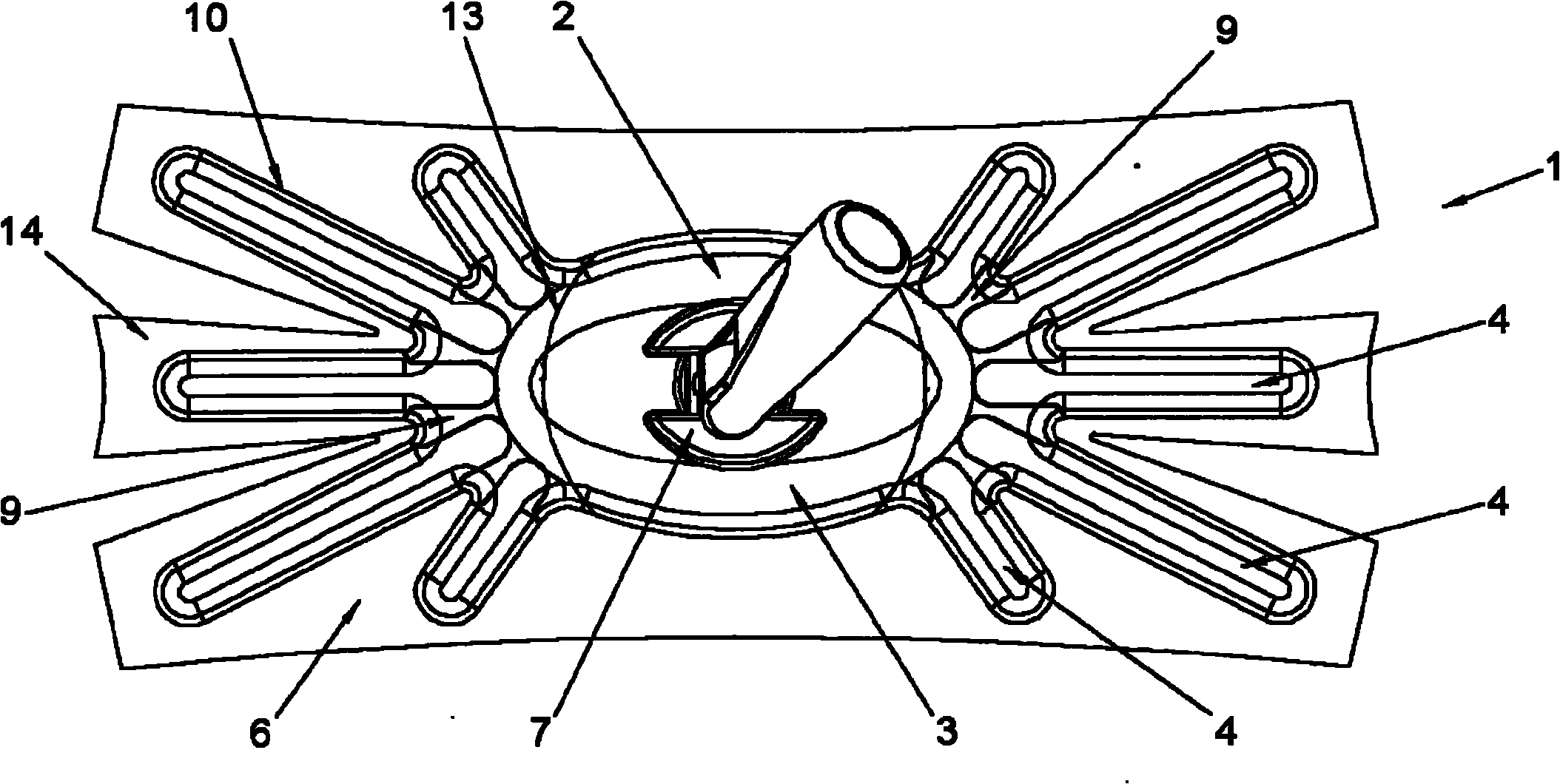
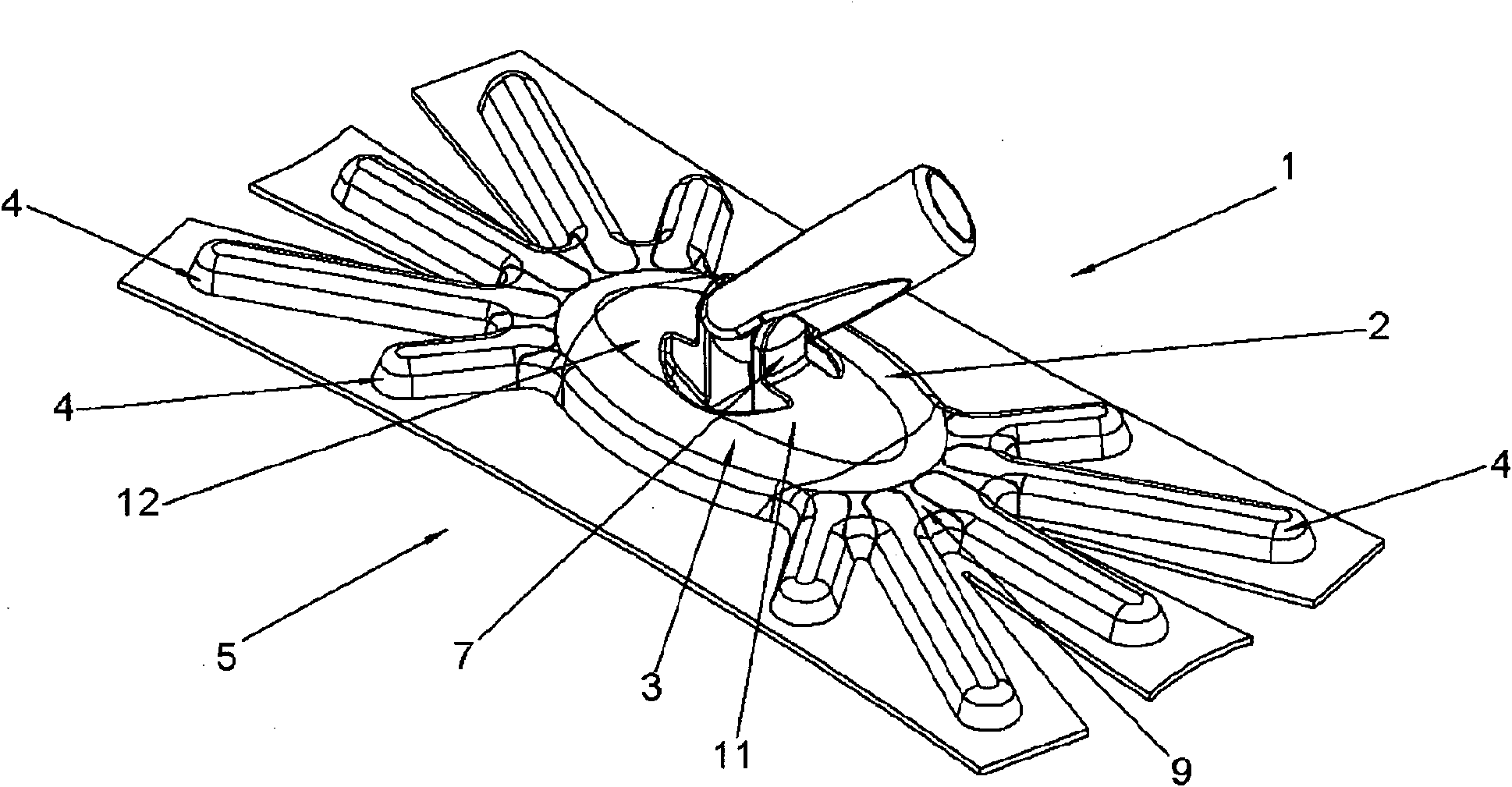
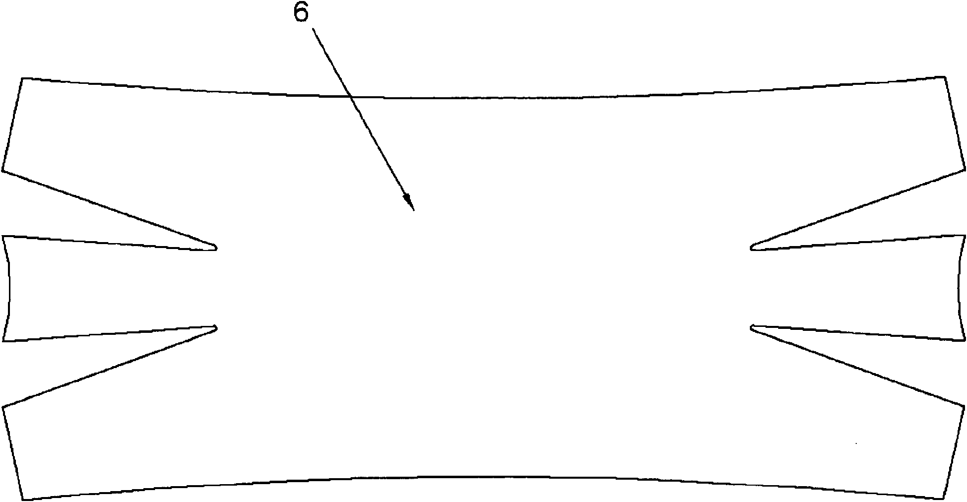
[0030] figure 1 A cleaning device 1 designed as a dust wiper for dry cleaning is shown. The cleaning device 1 comprises a wiping board 2 with a central area 3 from which five arms each extend in a star-shaped manner to both sides. A cleaning cloth 6 is fastened releasably on the cleaning surface 5 of the wiper 2 , ie on the underside, by means of an attachment mechanism 10 in the form of a Velcro. In this case, the cleaning cloth 6 rests flat on the floor to be cleaned in the section assigned to the central area 3 and in a straight line on the floor to be cleaned in the section assigned to the arms 4 . A shank connection 7 is integrated into the central area 3 . The arms 4 are connected in a star shape to the central region 3 and are formed and arranged such that the wiper 2 has a rectangular boundary. The arms 4 are elastically fastened to the central region 3 via connecting webs 8 , wherein the arms 4 , connecting webs 8 and central region 3 are made of the same material ...


PUM


Abstract

The invention relates to a cleaning appliance (1) comprising a wiper plate (2) having a central region (3) from which a plurality of arms (4) extend on both sides, the wiper plate (2) comprising a cleaning side (5) to which a cleaning cloth (6) can be fixed. Said cleaning cloth is placed on the floor to be cleaned, with a flat surface in the section associated with the central region (3), and essentially linearly in the sections associated with the arms (4).

Description

technical field [0001] The invention relates to a cleaning appliance having a wiper plate with a central region. Background technique [0002] Cleaning devices are known from the prior art which are used for cleaning hard-to-reach places. In particular, cleaning devices for wiping dust can also be used in hard-to-reach places, since a particularly large amount of dust often accumulates there. The cleaning appliance shown in EP 1 097 667 B1 is particularly suitable for cleaning floors in the vicinity of heating pipes. For this purpose, the cleaning appliance has recesses in its wiper plate in the area of ​​the narrow sides, into which the heating ducts can penetrate during cleaning, so that the floor in the area of ​​the heating ducts can also be cleaned. Although this cleaning device has a high level of cleaning efficiency due to its planar configuration, it can only clean around objects whose longitudinal extension is smaller than the width of the opening. Contents of t...

Claims


Application Information

Patent Timeline
Patent Type & Authority Applications(China)
IPC IPC(8): A47L13/256A47L13/20
CPCA47L13/20A47L13/256
Inventor U·丁格特H·J·克莱门
Owner CARL FREUDENBERG KG
Learn More