A clamping device driven by a deceleration motor

A technology of deceleration motor and clip opener, applied in the direction of electrolysis process and electrolysis components, can solve the problems affecting the service life and safety of equipment, and achieve the effect of improving reliability

Active Publication Date: 2015-08-05
JUNJIE MACHINERY SHENZHEN
View PDF8 Cites 0 Cited by
  • Summary
  • Abstract
  • Description
  • Claims
  • Application Information

AI Technical Summary

Problems solved by technology

Affect the service life and safety of the equipment

Method used


Image

  • A clamping device driven by a deceleration motor
  • A clamping device driven by a deceleration motor
  • A clamping device driven by a deceleration motor

Examples


Embodiment Construction

[0019] The present invention will be described in further detail below according to accompanying drawing and embodiment:

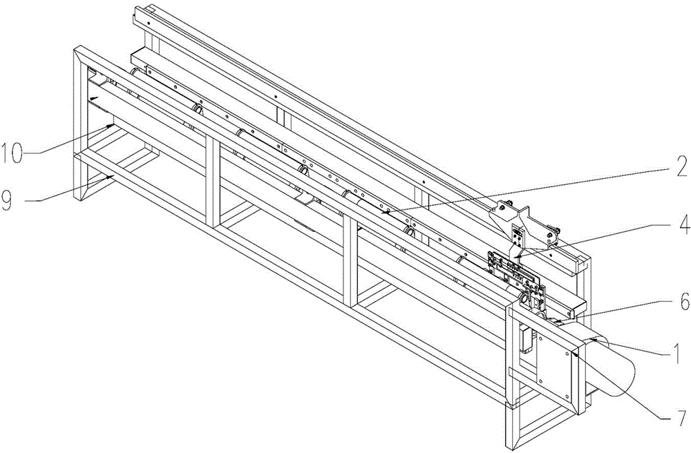
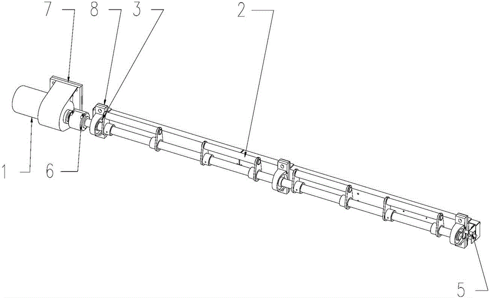
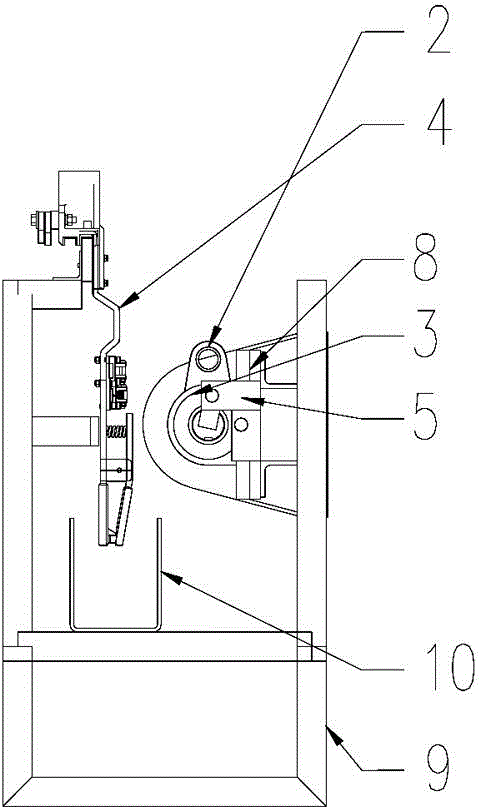
[0020] As shown in the figure, this embodiment provides a deceleration motor-driven clamp opening device, which includes a deceleration motor 1, a clamp opener 2 and a rotating shaft 3, the deceleration motor 1 drives the rotation shaft 3 to rotate, and the rotation At least one clip opener 2 that rotates with the rotating shaft 3 is fixed on the shaft 3 , and the clip opener 2 cooperates with the clamp 4 . The reduction motor 1 drives the rotation shaft 3 to rotate, and the clip opener 2 on the rotation shaft 3 swings with the rotation shaft 3. After swinging to contact with the clamp 4, the splint of the clamp 4 is pressed down due to the action of the reduction motor 1, and the clamp 4 is opened. .

[0021] It also includes an inductor 5 , which senses the opening and closing position of the clamp 6 , and when sensing that the clamp 6 is fully opened, ...


PUM


Abstract

The invention provides a gear-motor-driven unclamping device, comprising a gear motor, an unclamp device and a rotational shaft, wherein the gear motor drives the rotational shaft to rotate, the rotational shaft is at least fixedly provided with one unclamping device rotating along with the rotational shaft, and the unclamping device is matched with a clamp. The gear motor drives the rotational shaft to rotate, the unclamping device on the rotational shaft swings along with the rotational shaft, and when the unclamping device swings to a position to be in contact with the clamp, a splint of the clamp is pressed down under the action of the gear motor so as to unclamp the clamp. The gear-motor-driven unclamping device provided by the invention is safe and reliable and is far away from a stripping and hanging groove.

Description

technical field [0001] The invention relates to the field of PCB electroplating, in particular to a clamping device driven by a deceleration motor in the field of PCB electroplating. Background technique [0002] In the field of PCB electroplating, air cylinder clamping is generally used at present, because the stripping potion is generally nitric acid or sulfuric acid plus hydrogen peroxide, which is extremely corrosive, and the cylinder is used for direct clamping. The cylinder is installed on the edge of the stripping tank, which is easily corroded and damaged. Affect the service life and safety of the equipment. Contents of the invention [0003] The technical problem to be solved by the present invention is to provide a deceleration motor-driven clip opening device, which is safe and reliable, and is far away from the stripping groove. [0004] The technical scheme that the present invention adopts for solving the problems of the technologies described above is: [...

Claims


Application Information

Patent Timeline
Patent Type & Authority Patents(China)
IPC IPC(8): C25D17/08
Inventor 李伯仲
Owner JUNJIE MACHINERY SHENZHEN
Why Eureka
Try Eureka