Liquid crystal display and backlight module thereof

A liquid crystal display and backlight module technology, which is applied in the direction of instruments, optics, light guides, etc., can solve the problems of cost increase and achieve the effect of improving light spots and increasing light distribution intensity

Active Publication Date: 2012-08-15
AU OPTRONICS CORP
View PDF0 Cites 2 Cited by
  • Summary
  • Abstract
  • Description
  • Claims
  • Application Information

AI Technical Summary

Problems solved by technology

This light problem can be solved by reducing the pitch P, but when the pitch P is reduced, the manufacturer must use a larger number of LED elements 124, resulting in an increase in cost

Method used


Image

  • Liquid crystal display and backlight module thereof
  • Liquid crystal display and backlight module thereof
  • Liquid crystal display and backlight module thereof

Examples


no. 1 example

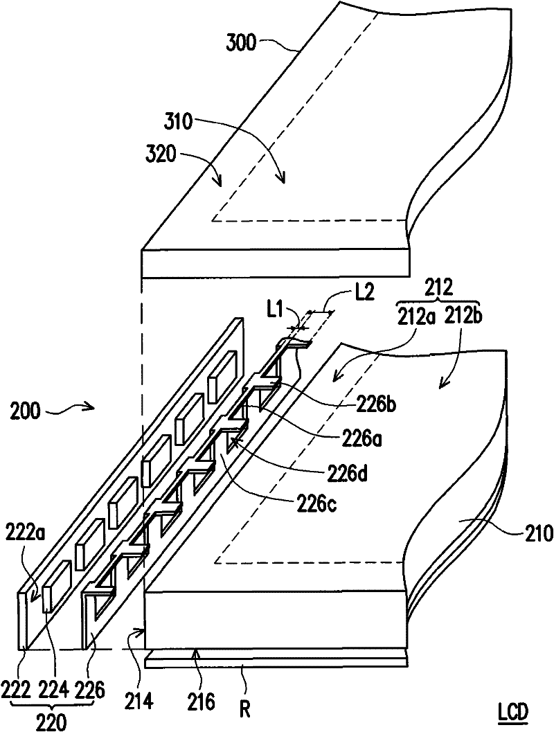
[0065] figure 2 is a schematic diagram of the liquid crystal display of the first embodiment of the present invention, and image 3 It is a schematic top view of the backlight module according to the first embodiment of the present invention. Please refer to figure 2 , the liquid crystal display LCD of this embodiment includes a backlight module 200 and a liquid crystal display panel 300 , wherein the liquid crystal display panel 300 is disposed above the backlight module 200 . In this embodiment, the liquid crystal display panel 300 is, for example, a transmissive LCD panel or a transflective LCD panel.

[0066] Such as figure 2 and image 3 As shown, the backlight module 200 includes a light guide plate 210 and a linear light source 220 . The light guide plate 210 has a top light exit surface 212 and a side light incident surface 214 connected to the top light exit surface 212, and the top light exit surface 212 includes a peripheral area 212a connected to the side l...

no. 2 example

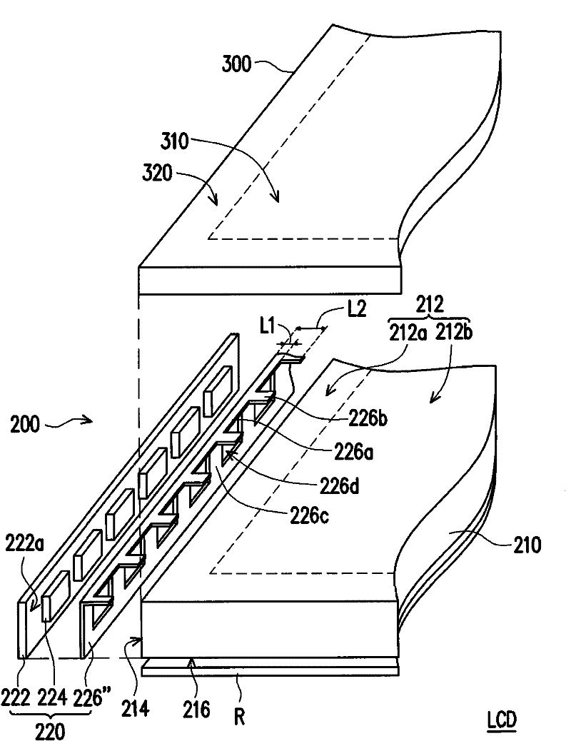
[0076] Figure 4 It is a schematic diagram of a liquid crystal display according to a second embodiment of the present invention. Please refer to Figure 4 , the liquid crystal display LCD' of the present embodiment is similar to the liquid crystal display LCD of the first embodiment, but the main difference between the two is that: the reflector 226' of the present embodiment includes a first reflective portion 226a, a second reflective portion 226b and an assembly part 226c' connected to the linear light source 220, the assembly part 226c' is connected to the first reflection part 226a and the second reflection part 226b, and the assembly part 226c' includes a plurality of strip structures S, and each solid state light emitting element 224 are respectively located between two adjacent strip structures S. For example, the aforementioned assembly part 226c' is fixed on the circuit board 222 by glue or other methods.

[0077] Figure 4' It is a schematic diagram of another ...


PUM


Abstract

The invention discloses a liquid crystal display and a backlight module thereof. The backlight module comprises a light guide plate and a linear light source. The light guide plate has a top light leaving face and a lateral light incident face, wherein the top light leaving face comprises a peripheral area and an effective lighting area. The linear light source comprises a circuit board, a plurality of solid light emitting elements and a reflector. The solid light emitting elements are configured on the circuit board and are electrically connected with the circuit board, the light beams provided by the solid light emitting elements enter the light guide plate from the lateral light incident face, and the reflector covers part of the peripheral area. In addition, the reflector comprises a plurality of reflecting parts corresponding to the solid light emitting elements and a plurality of second reflecting parts connected between each two adjacent first reflecting parts, the first and second reflecting parts extend toward the direction of the effective lighting area from the edge of the top light leaving face, and the extended length of the first reflecting parts is smaller than thatof the second reflecting parts. In the invention, the light spots generated by the backlight module can be effectively improved.

Description

technical field [0001] The present invention relates to a liquid crystal display (liquid crystal display, LCD), and in particular to a backlight module. Background technique [0002] Liquid crystal displays have become the main focus of display research in recent years because of their low-voltage operation, no radiation scattering, light weight, and small size, which cannot be achieved by displays made of traditional cathode ray tubes (CRTs). issues, and is constantly developing towards colorization. [0003] Since the liquid crystal display is a non-self-illuminating display, it needs the backlight module to provide the required light to achieve the display function. In recent years, with the improvement of environmental awareness, the light-emitting elements used in the backlight module have been gradually converted from cold cathode fluorescent lamps (CCFL) to more environmentally friendly light-emitting diode elements. When the light emitting diode element is applied ...

Claims


Application Information

Patent Timeline
Patent Type & Authority Patents(China)
IPC IPC(8): G02F1/13357F21S8/00F21V19/00F21V7/00F21V8/00
Inventor 张芷娟黄昱琮刘曜旗
Owner AU OPTRONICS CORP
Why Eureka
Try Eureka