Press-contact pogo pin connector

一种压接型、连接器的技术,应用在连接、连接装置的零部件、耦合装置等方向,能够解决不能充分满足低背性等问题,达到实现小型化、简单结构、容易多极化的效果

Active Publication Date: 2011-06-01
SMK CO LTD
View PDF9 Cites 14 Cited by
  • Summary
  • Abstract
  • Description
  • Claims
  • Application Information

AI Technical Summary

Problems solved by technology

[0009] above as Figure 12 In the connector shown in which the cylinder and thimble are formed by bending the plate, the processing cost and the instantaneous interruption performance against external impact can be improved, but the outer cylinder as the cylinder and the inner cylinder as the thimble are both made of metal. Processed products are manufactured and assembled into injection-molded housings. Therefore, there is a problem that the low-profile requirements for mounting such crimp-type connectors in a direction parallel to the substrate cannot be fully met.

Method used


Image

  • Press-contact pogo pin connector
  • Press-contact pogo pin connector
  • Press-contact pogo pin connector

Examples


Embodiment Construction

[0069] Next, embodiments of the present invention will be described based on examples shown in the drawings.

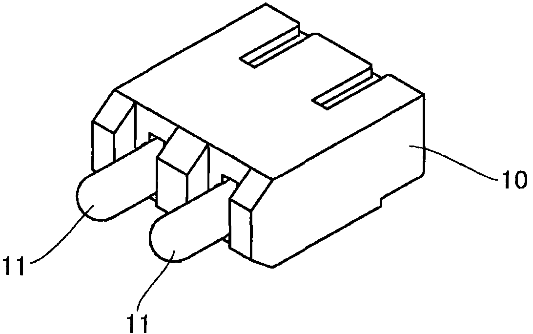
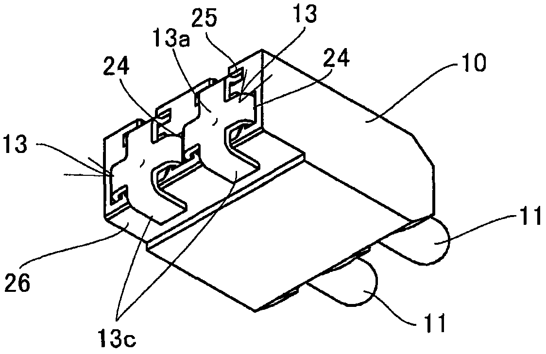
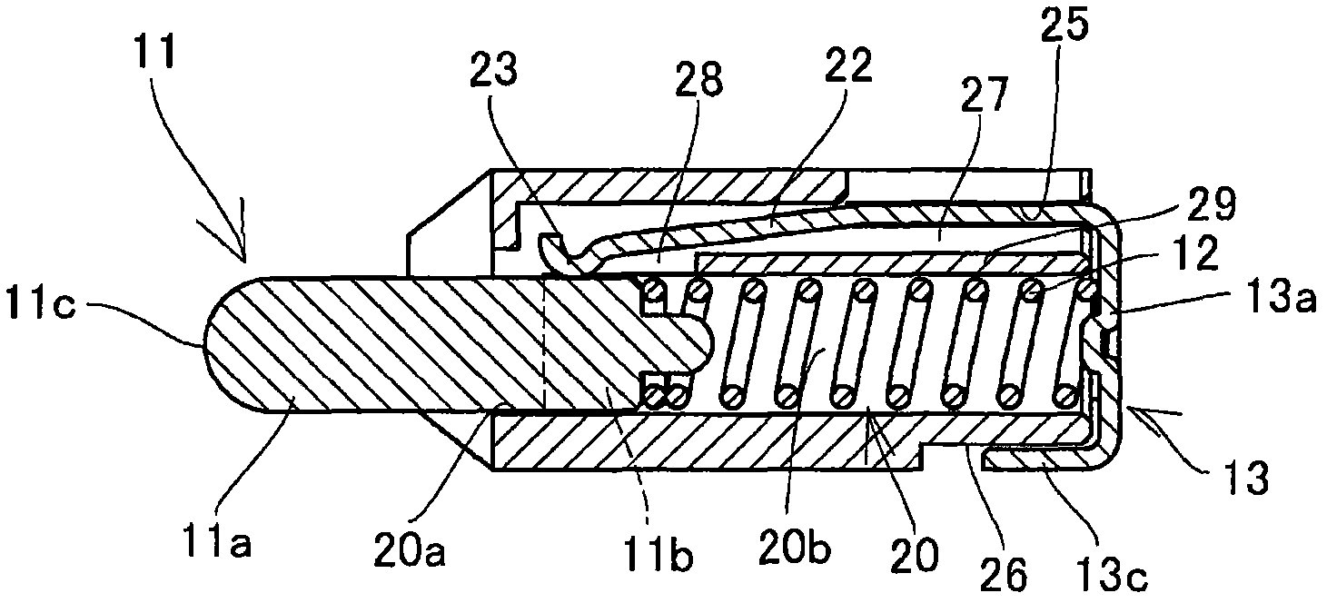
[0070] Figure 1 to Figure 7 This is the first embodiment of the ejector crimp connector of the present invention, showing an example used for a battery connector in which a plurality of ejector pins protrude elastically. The thimble crimp connector is composed of a housing 10 , a thimble 11 , a coil spring 12 and a contact 13 . A pair of thimbles 11 , 11 that can be freely entered and exited are assembled in the housing 10 .

[0071] The casing 10 is obtained by injection molding an insulating synthetic resin material, and is formed with a cylindrical hole 20 opening through the front and rear surfaces. The cylindrical hole 20 has a circular shape at the front opening 20a of the cylindrical hole on the front end of the casing, but the opening 20a on the front casing side of the cylindrical hole is closer to the contact point than the opening 20a on the front casing...


PUM


Abstract

A press-contact pogo pin connector is provided which has a machining cost lower than those of conventional connectors, can be easily reduced in height, and does not cause instantaneous interruption. A molded insulating housing has a cylinder hole in which a pin is installed, and the pin installed inside the cylinder hole is urged by a coil spring installed inside the cylinder hole so as to protrude from the housing. A flange portion on the rear side of the pin urged by the coil spring abuts against the peripheral portion of the front opening of the cylinder hole on the front side of the housing so that the pin is prevented from falling off. A contact integrally includes a substrate connection terminal portion and a contact spring portion that extends inside the cylinder hole and is brought into press-contact with the pin at all times. The contact is secured to the housing.

Description

technical field [0001] The invention relates to a thimble type crimping type connector mainly used as a battery connector in small electronic equipment such as a mobile phone. Background technique [0002] Conventionally, a crimp-type connector using ejector pins has been used as a battery connector for a mobile phone. [0003] Such as Figure 11 As shown, as a conventional thimble used in this type of crimping connector, the thimble 3 urged in the push-out direction by the coil spring 2 is housed in a metal bottomed cylindrical cylinder 1 so that it can come in and out freely. Under the biasing force of the coil spring 2 in the protruding direction, the front end of the crimping pin portion 3a of the thimble 3 protrudes from the front end of the cylinder 1, and is crimped to the contact terminal portion of the battery. [0004] A beveled surface 4 inclined relative to the axial direction is formed on the inner end surface of the cylinder of the thimble 3, and the surface i...

Claims


Application Information

Patent Timeline
Patent Type & Authority Applications(China)
IPC IPC(8): H01R13/502
CPCH01R13/2421
Inventor 浅井清土桥学
Owner SMK CO LTD
Why Eureka
Try Eureka