Forging and stamping die of brake cylinder seat

A technology of brake cylinders and molds, which is applied in the manufacture of tools, forging/pressing/hammer devices, forging/pressing/hammering machines, etc., to achieve the effects of low forging cost, stable forging quality and long service life

Inactive Publication Date: 2011-06-08
WUHU XINDA FORGING
View PDF0 Cites 4 Cited by
  • Summary
  • Abstract
  • Description
  • Claims
  • Application Information

AI Technical Summary

Problems solved by technology

[0003] The object of the present invention is to provide a forging die for a brake cylinder seat, which solves the problem that excessive metal blanks are extruded from the die cavity during forging

Method used


Image

  • Forging and stamping die of brake cylinder seat
  • Forging and stamping die of brake cylinder seat
  • Forging and stamping die of brake cylinder seat

Examples


Embodiment 1

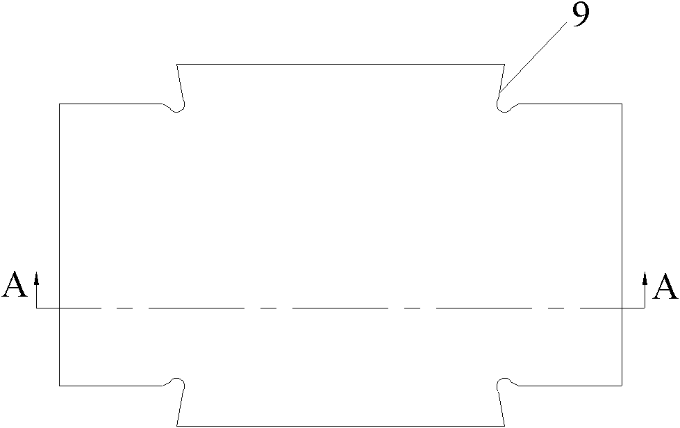
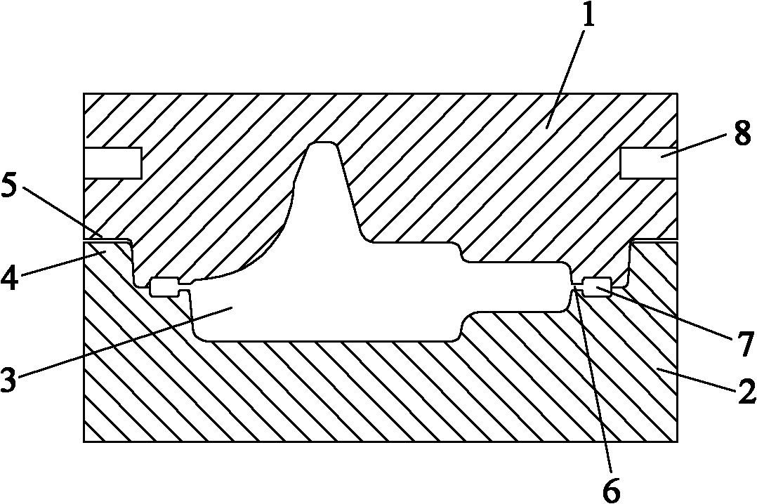
[0014] Example 1, such as Figure 1 to Figure 2 Shown, a kind of forging die of brake cylinder block, it comprises die cavity 3 that forms between upper die 1 and lower die 2 and upper die 1, lower die 2; Described upper die and lower die pass through upper die The concave lock 5 and the convex lock 4 of the lower mold are adapted for positioning, and the concave lock 5 is a concave gap provided around the lower end of the upper mold, and the convex lock 4 is a protrusion provided around the upper end of the lower mold; in order to ensure that the upper mold It can fully contact with the mold surface of the lower mold so as not to make a wrong mold, and there is a gap of 3mm between the concave lock of the upper mold and the convex lock of the lower mold. A flash groove 7 is also arranged on the edge of the mold cavity between the upper mold and the lower mold; a flash bridge portion 6 is arranged between the mold cavity 3 and the flash groove 7, and the flash bridge portion ...


PUM


Abstract

The invention discloses a forging and stamping die of a brake cylinder seat, which comprises an upper die and a lower die, and a die cavity formed between the upper die and the lower die, wherein the upper die and the lower die are matched and positioned through a concave lock catch of the upper die and a convex lock catch of the lower die, a flash cavity is arranged on the edge of the die cavity between the upper die and the lower die, and a flash bridge part is arranged between the die cavity and the flash cavity. Furthermore, the distance from the upper die to the lower die at the flash bridge part is 1/3 of that from the upper die to the lower die at the flash cavity. During the forging, a metal blank is not easy to extrude out of the die cavity during the forging to ensure that the forged forging has stable quality; and the die has long service life and low forging cost.

Description

technical field [0001] The invention relates to a forging die, in particular to a forging die for a brake cylinder seat. Background technique [0002] Most of the current forging dies include an upper die and a lower die and a die cavity formed between the upper die and the lower die. Product quality and manufacturing cost are very important to manufacturing enterprises. At present, the metal billet is easily squeezed out of the die cavity during the forging process, resulting in the phenomenon of product lack of meat due to excessive metal being squeezed out of the die cavity, resulting in poor product quality or even scrapped . If the flash of the forging is squeezed onto the upper and lower die surfaces during the forging process, the wear of the die face will be aggravated during the continuous forging process, the life of the die will be reduced, and the forging cost will be increased. Contents of the invention [0003] The object of the present invention is to pro...

Claims


Application Information

Patent Timeline
Patent Type & Authority Applications(China)
IPC IPC(8): B21J13/02
Inventor 刘争辉张会续王雪裴学成
Owner WUHU XINDA FORGING
Why Eureka
Try Eureka