
Uplink power detection method, device and base station equipment

A power detection and power technology, applied in power management, error detection/prevention using signal quality detector, transmission modification based on link quality, etc. Problems such as dropped calls

Active Publication Date: 2011-06-08
HUAWEI TECH CO LTD
View PDF5 Cites 22 Cited by
  • Summary
  • Abstract
  • Description
  • Claims
  • Application Information

AI Technical Summary

Problems solved by technology

However, in network planning, there is a phenomenon of unbalanced uplink and downlink power, so the uplink coverage may be limited before the downlink coverage, that is, the uplink coverage is already limited when the downlink coverage is not limited.
Especially in the scenario where there is uplink interference, the UE's uplink transmit power is more likely to be limited before the downlink, resulting in the uplink coverage being limited before the downlink coverage
If the UE's uplink transmit power is limited, call drop is more likely to occur
[0003] The problem existing in the cell handover method in the prior art is: the handover is triggered by the quality of the downlink signal, which cannot accurately characterize the situation where the uplink signal is limited. When the uplink coverage is limited before the downlink coverage, because the downlink signal quality has not The threshold value for triggering handover is reached, so the handover will not be triggered, which makes the UE prone to call drop

Method used


Image

  • Uplink power detection method, device and base station equipment
  • Uplink power detection method, device and base station equipment
  • Uplink power detection method, device and base station equipment

Examples


Embodiment Construction

[0018] In order to make the objectives, technical solutions, and advantages of the embodiments of the present invention clearer, the technical solutions in the embodiments of the present invention will be described clearly and completely in conjunction with the accompanying drawings in the embodiments of the present invention. Obviously, the described embodiments It is a part of the embodiments of the present invention, not all the embodiments. Based on the embodiments of the present invention, all other embodiments obtained by those of ordinary skill in the art without creative work shall fall within the protection scope of the present invention.

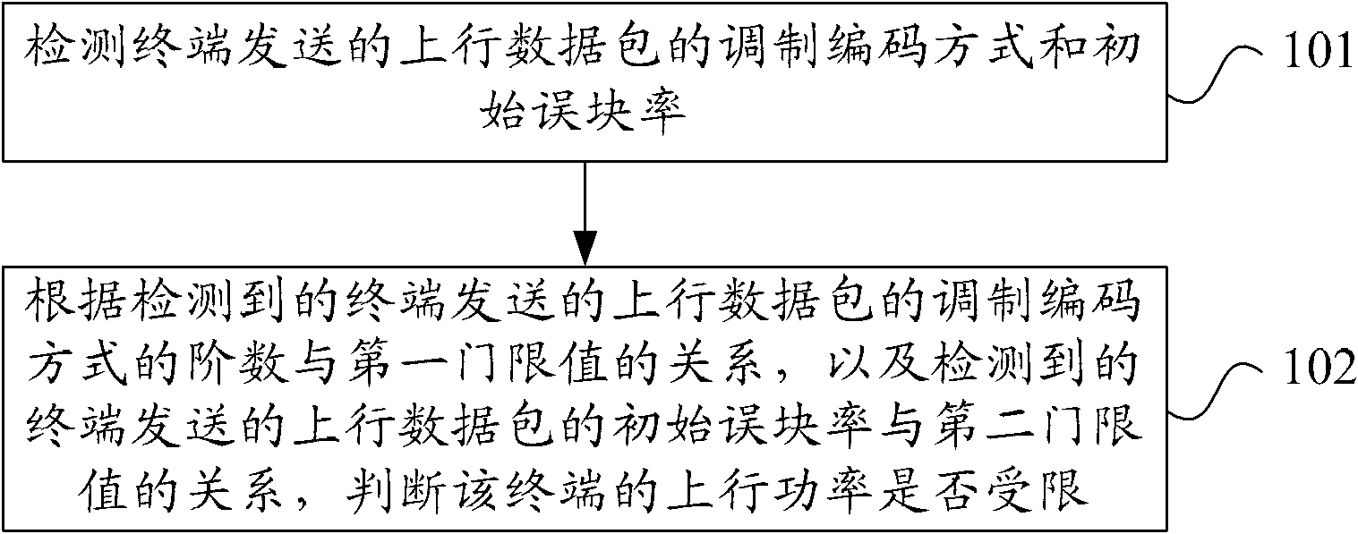
[0019] figure 1 Is a flowchart of an uplink power detection method provided by an embodiment of the present invention, such as figure 1 As shown, the method includes:

[0020] Step 101: Detect the modulation and coding mode and the initial block error rate of the uplink data packet sent by the terminal.

[0021] For an uplink data packet...


PUM


Abstract

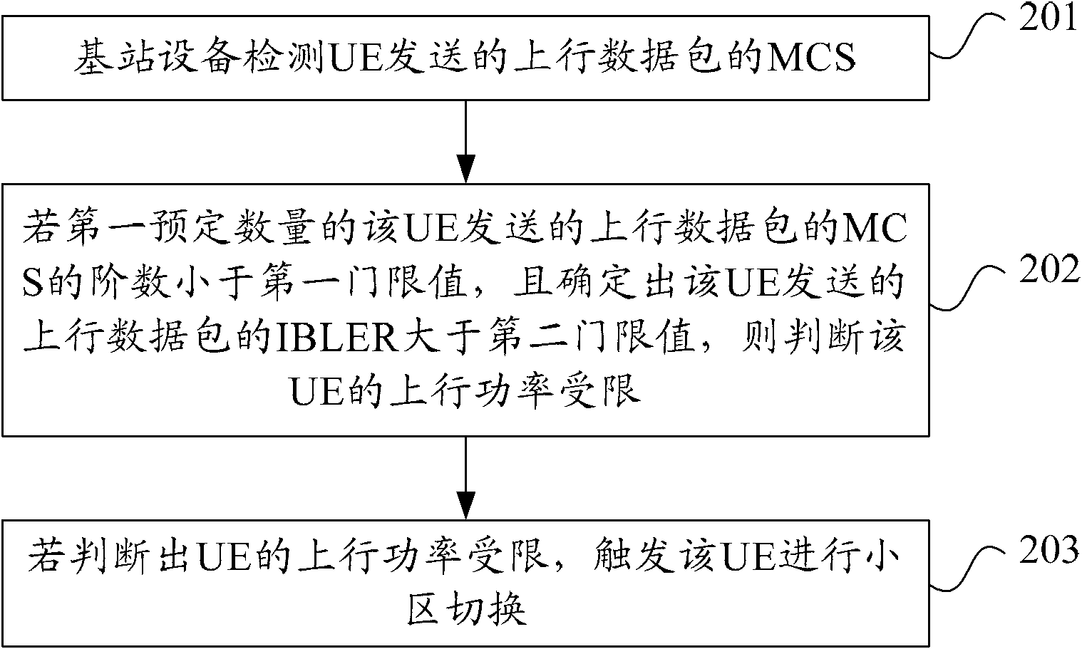
The embodiment of the present invention provides an uplink power detection method, a device and base station equipment, wherein the method comprises the steps of: detecting modulation and coding scheme and initial block error rate of an uplink data packet sent by a terminal; and determining whether the uplink power of the terminal is confined according to the relationships between the order of the detected modulation and coding scheme of the uplink data packet sent by the terminal and a first threshold, and between the detected initial block error rate of the uplink data packet sent by the terminal and a second threshold. The base station equipment provided by the embodiment of the invention detects modulation coding scheme and initial block error rate of an uplink data packet sent by a User Equipment (UE) and determines whether the uplink power of the UE is confined according to the detected modulation and coding scheme and the detected initial block error rate, thereby being able to precisely characterize the condition that the uplink signal of the UE is confined.

Description

Technical field [0001] The embodiments of the present invention relate to the field of communication technologies, and in particular, to an uplink power detection method, device, and base station equipment. Background technique [0002] When the network coverage is limited, the base station will trigger a cell handover. Existing cell handovers are all triggered by downlink signal quality, that is, when the downlink signal quality is lower than a certain threshold, a terminal (User Equipment, hereinafter referred to as UE) is triggered to perform cell handover. In network planning, there is a phenomenon of unbalanced uplink and downlink power. As a result, the uplink coverage may be limited before the downlink coverage, that is, the uplink coverage is already limited when the downlink coverage is not yet limited. Especially in scenarios where there is interference in the uplink, the uplink transmit power of the UE is more likely to be limited before the downlink, which results in...

Claims


Application Information

Patent Timeline
IPC IPC(8): H04W24/08H04W52/00H04W88/08
CPCH04W52/367H04W36/24H04L1/0045H04W52/146H04B17/0077H04W52/262H04W52/04H04L1/0026H04L1/20H04B17/0057H04L1/0025H04W52/265H04L27/0012H04W36/0077H04B17/382H04W36/00837H04W36/249H04W24/10
Inventor 涂靖
Owner HUAWEI TECH CO LTD
Learn More