Dynamic jet flow energy-saving demister
A demister and jet technology, applied in the direction of chemical instruments and methods, dispersed particle separation, combined devices, etc., can solve the problems of poor corrosion resistance, easy scaling, inconvenient washing, etc., to increase the collection area, improve the collection The effect of collecting efficiency and reducing pressure drop loss
- Summary
- Abstract
- Description
- Claims
- Application Information
AI Technical Summary
Problems solved by technology
Method used
Image

Examples
Embodiment 1
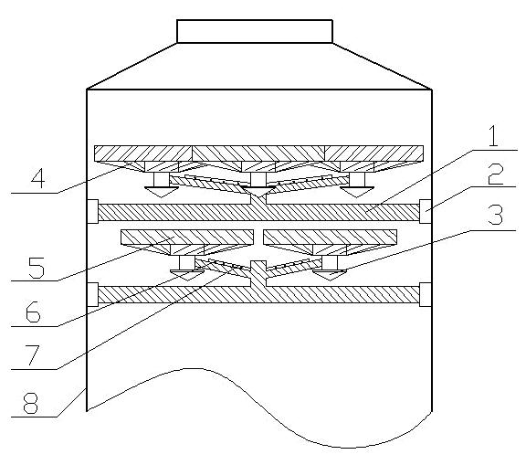
[0025] Embodiment one: see figure 1 with figure 2 , the dynamic jet energy-saving mist eliminator, including the tower body 8 of the absorption tower, the upper part of the inner cavity of the tower body 8 is equipped with two layers of dynamic jet defogging mechanism, each layer of dynamic jet defogging mechanism includes four purification units, one "米" character supporting part 1 and the connecting piece 2 fixedly connected with the tower body 8, each said purifying unit consists of a rotating drainage body 3, a plurality of blades 4 with inclined angles connected around the rotating drainage body, The cover bar 5 connected with the outer end of the blade and the controllable water spray device installed on the "rice" character support part 1 constitute.
Embodiment 2
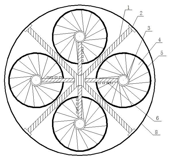
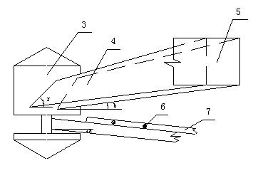
[0026] Embodiment 2: This embodiment is basically the same as Embodiment 1, and the more detailed structure is described in detail as follows: the four purification units are evenly distributed on the same circular surface in the circumferential direction, and are fixedly installed on the "rice" character support member 1 respectively. The ends of the other four poles of the "meter" character supporting part 1 are fixedly connected with the tower body 8 through the connecting piece 2. There are 45 o rotation staggered. The structure of the rotating drainage body 3: an upper cone is connected to a lower cone through a middle cylinder, and the apex angle between the upper cone and the lower cone is 90° o ~150 o , the middle cylinder is fixedly connected with the blade 4 . The blade 4 has an elevation angle b with the horizontal plane, and the elevation angle b=8 o ~16 o . The controllable water spraying device is to fix a water delivery pipe 7 on the pole on which the rota...
Embodiment 3
[0027] Embodiment three: as figure 2 As shown, the dynamic jet energy-saving mist eliminator has two layers, and each layer includes four purification units, a "meter" character supporting part 1 and a connecting part 2 with the tower body. Each purification unit consists of a rotating drainage body 3, a plurality of blades 4 with inclined angles connected around the rotating drainage body, a cover fence 5 connected to the outer end of the blades, and a controllable water spray device (water delivery pipe 7 and nozzle 6). composition. The four purification units are arranged in four positions up, down, left, and right in the same circular surface, and are supported by four support rods drawn from the center of the "meter" character support part 1. The inclination angle between the support rod and the horizontal direction is 10 o , it is convenient for the liquid on the support bar to gather toward the center and fall into the slurry pool. Place the water delivery pipe 7 on ...
PUM
| Property | Measurement | Unit |
|---|---|---|
| thermal resistance | aaaaa | aaaaa |
Abstract
Description
Claims
Application Information
 - R&D Engineer
- R&D Manager
- IP Professional
- Industry Leading Data Capabilities
- Powerful AI technology
- Patent DNA Extraction
Browse by: Latest US Patents, China's latest patents, Technical Efficacy Thesaurus, Application Domain, Technology Topic.
© 2024 PatSnap. All rights reserved.Legal|Privacy policy|Modern Slavery Act Transparency Statement|Sitemap