Bearing structure, and propeller device equipped with such bearing structure

A technology of supporting structure and propeller, applied in the direction of rotating propeller, bearing, mechanical equipment, etc., can solve problems such as failure, increase of supporting structure, wear and so on

Inactive Publication Date: 2011-06-15
MARIFIN BEHEER
View PDF7 Cites 4 Cited by
  • Summary
  • Abstract
  • Description
  • Claims
  • Application Information

AI Technical Summary

Problems solved by technology

The consequence is that the support structure is thus subject to increased wear and will eventually fail

Method used


Image

  • Bearing structure, and propeller device equipped with such bearing structure
  • Bearing structure, and propeller device equipped with such bearing structure
  • Bearing structure, and propeller device equipped with such bearing structure

Examples


Embodiment Construction

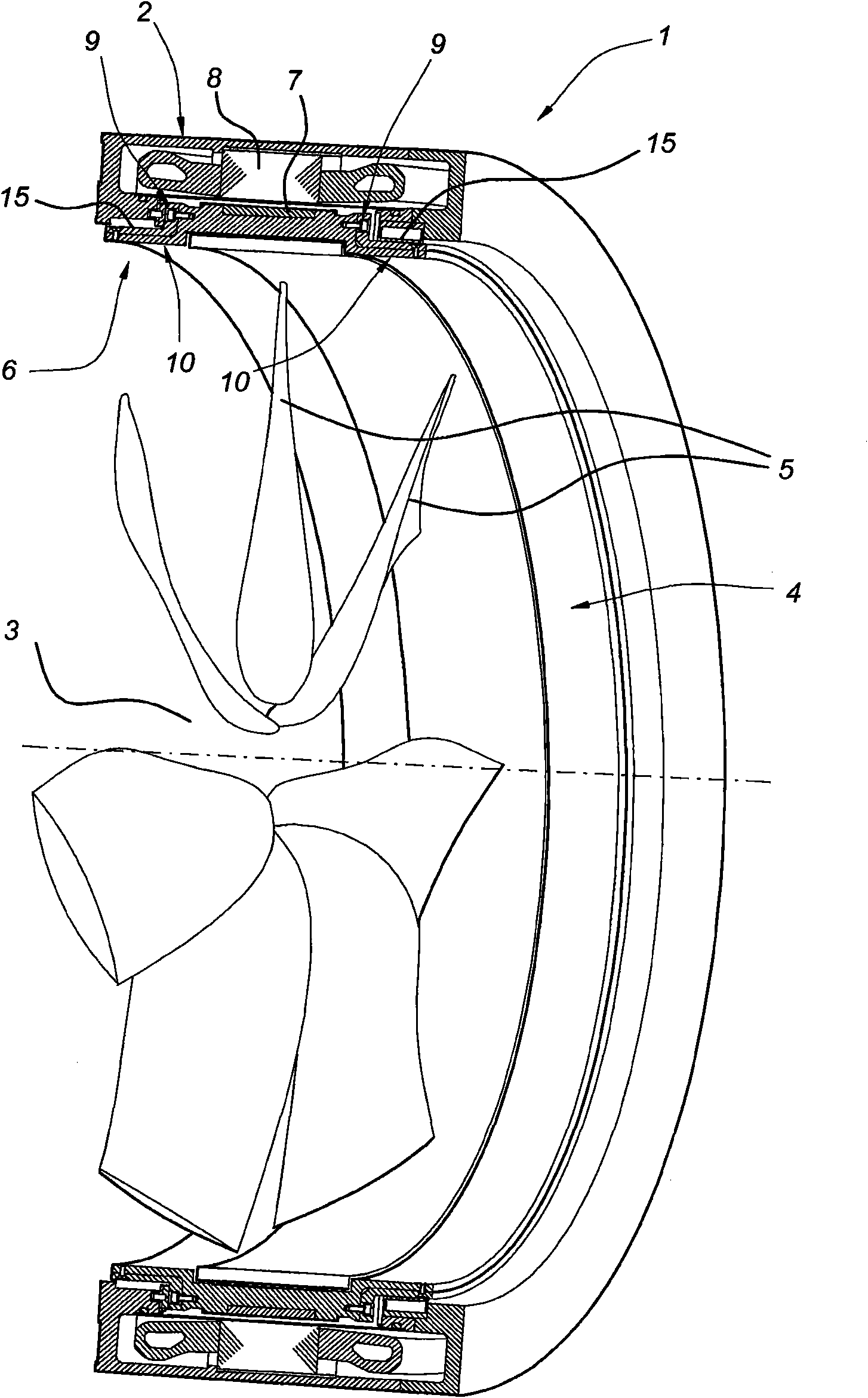
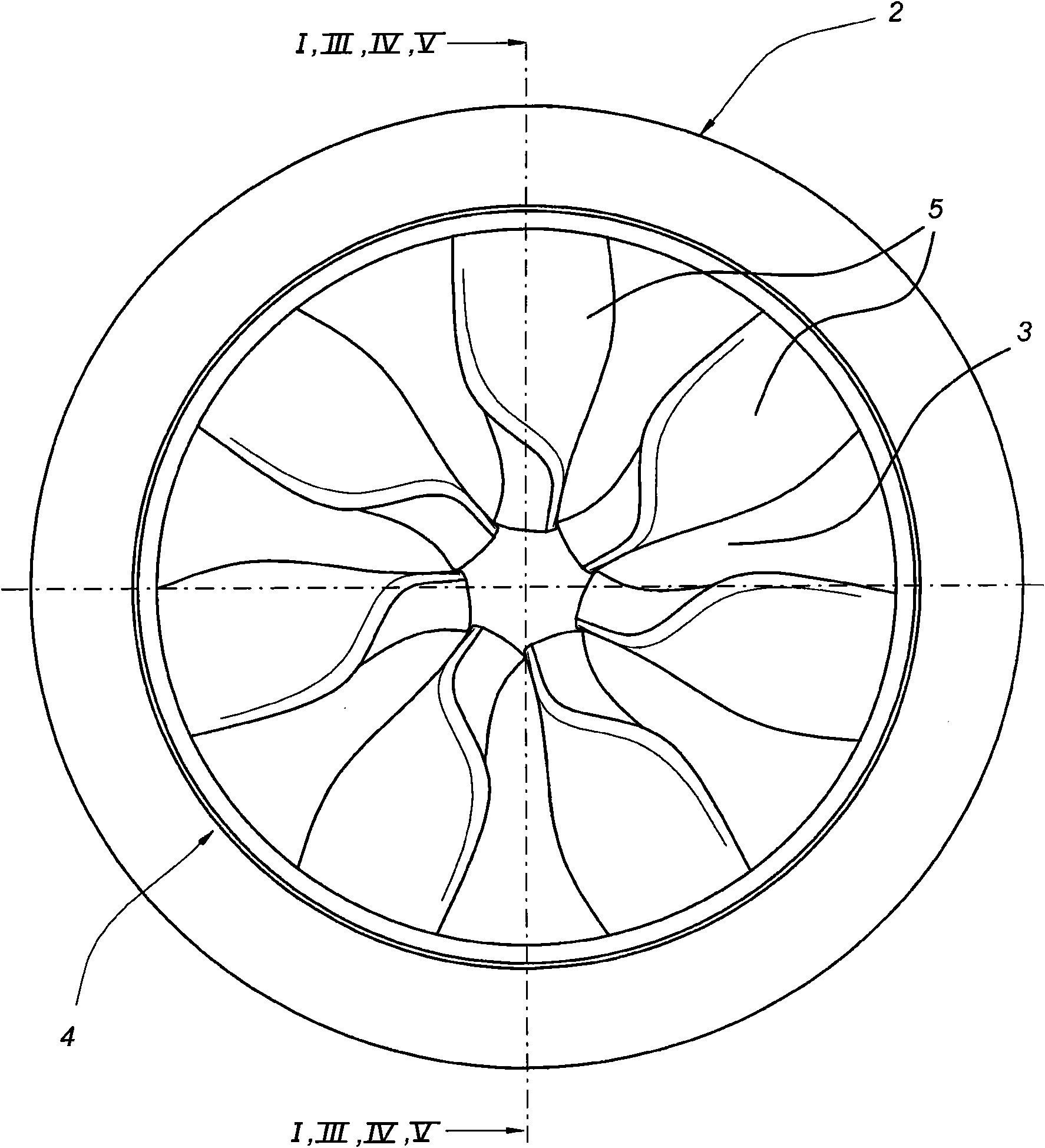
[0022] According to the present invention and in figure 1 and figure 2 The propeller shown in includes a sleeve indicated as a whole by reference numeral 2 and comprising a circular opening 3 . A rotor 4 is mounted in this opening 3 . The rotor 4 has an annular rotor body 6 and propeller blades 5 protruding inwardly from the annular rotor body 6 . Along the circumference of the annular rotor body 6 , the annular rotor body 6 is provided with permanent magnets 7 which can cooperate with stator windings 8 arranged around the opening 3 of the sleeve 2 and serve to drive the rotor 4 .

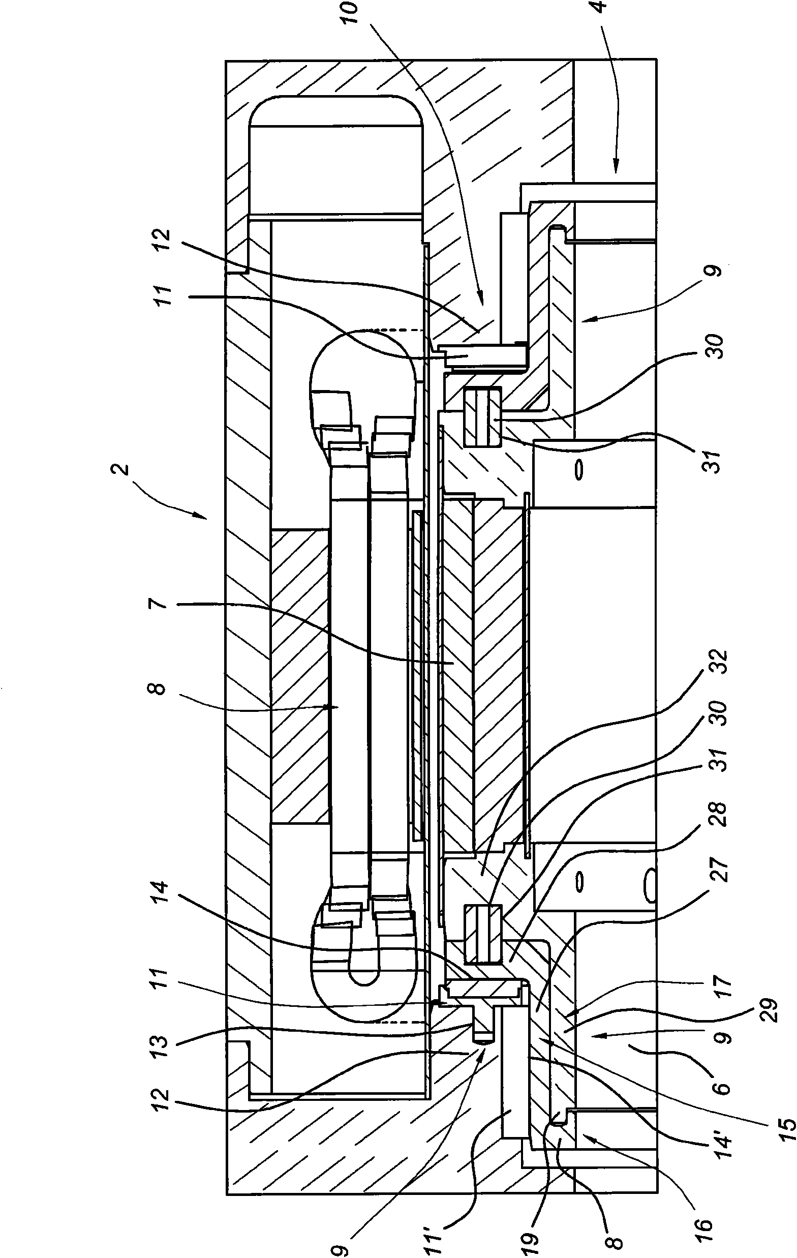
[0023] The rotor 4 is suspended in the sleeve 2 by a support structure having an axial support 9 and a radial support 10 at each axial end. The axial bearing 9 can absorb opposing axial forces, which makes it possible to drive the propeller in both directions. exist Figure 3-5 , these supports 9, 10 are shown on an enlarged scale, ie according to figure 2 The longitudinal section is shown ...


PUM


Abstract

A bearing structure between a rotor (4) and a sleeve (2), such as in a screw device, includes at least one axial bearing (9) and one radial bearing (10). Each bearing including a series of tilting pads (11, 11') extending in the peripheral direction and which are each suspended from a pad suspension area (12) of one of either the rotor (4) or the sleeve (2) by pad fastenings (13) which allow tilting, each tilting pad (11, 11') having a contact surface (14, 14'). Furthermore, each bearing including a bearing ring (15) which is situated opposite the series of tilting pads (11, 11') and cooperates with the contact surfaces thereof. The bearing ring is suspended from a bearing ring suspension area (17) of the other of either the rotor or the sleeve by bearing ring fastenings (16). The bearing ring fastenings allow contraction and expansion movements of the bearing ring.

Description

technical field [0001] The invention relates to a support structure between the rotor and the sleeve as in a shaftless propeller arrangement, the support structure comprising at least one axial support and one radial support, each of said axial support and radial support comprising a series of tilting pads extending in a peripheral direction and a support ring positioned opposite the series of tilting pads, wherein the tilting pads are each secured by a pad allowing tilting member suspended from a pad suspension region of one of the rotor and sleeve, the tilting pads each having a contact surface, the support ring cooperating with the contact surfaces of the series of tilting pads and passing through A back-up ring fastener is suspended from a back-up ring suspension region of the other of the rotor and the sleeve. The axial bearing absorbs axial loads directed along the axis of rotation of the bearing structure. Radial bearings absorb radial loads directed transversely to t...

Claims


Application Information

Patent Timeline
Patent Type & Authority Applications(China)
IPC IPC(8): B63H1/16
CPCF16C17/065B63H23/24F16C17/035B63H2023/005B63H2001/165B63H5/14F16C17/22F16C2326/30
Inventor 埃德温·西蒙·万布莱恩
Owner MARIFIN BEHEER
Why Eureka
Try Eureka