Method to improve the dimensional accuracy and surface quality for large spring back compensation for fuel cell bipolar plate forming

a fuel cell bipolar plate and compensation technology, applied in the field of stamping parts, can solve the problems of severe surface distortion, lateral (in-plane) spring back, and affecting functionality, and achieve stable and reliable surface compensation, high accuracy and surface quality

Active Publication Date: 2015-04-14
GM GLOBAL TECH OPERATIONS LLC
View PDF29 Cites 1 Cited by
  • Summary
  • Abstract
  • Description
  • Claims
  • Application Information

AI Technical Summary

Benefits of technology

[0011]In concordance with the instant disclosure, a method providing stable and reliable surface compensation with high accuracy and surface quality for large lateral spring back of fuel cell bipolar plates, to consistently meet the requirements of manufacturing and assembly, has surprisingly been discovered.
[0016]4. The second step morphing is based on the surface modified by the first stage morphing. The nominal shape is the output from the first stage morphing, and the target shape for compensation is the same data as used in the first stage morphing. A matrix of overlapping local morphing boxes is used to cover the entire plate so that the surface can be morphed to the required target details, for example, within 1 micron tolerance. In the second stage, the surface deformation within each local box is limited to very small amount (for example, a few microns to 20-30 microns compared to a few hundred microns of large spring back). Therefore, the surface distortion is avoided and a good surface quality can be achieved (i.e., same as an original CAD surface).
[0018]In another embodiment, the two step method of the present disclosure uses the global compensation to first morph surfaces for large nonlinear portion of spring back, and then employs a local morphing method to compensate the remaining spring back with the focus on the fine and detail features. The method advantageously provides compensated CAD surfaces with the same quality as the original design for both large and small spring back, and meets accuracy requirements, for example, 1 micron tolerance, consistently for large spring back. A file size of the compensated CAD file generated with the method is much smaller than with prior art methods. The compensated CAD also requires relatively short pre-processing time and computer run time, and can be used directly for machining purposes.

Problems solved by technology

However, the thin material and high strength of the stainless steel material cause significant lateral (in-plane) spring back.
The spring back causes an uneven distribution of a flow field stamped in the plate assembly, undesirably affecting a functionality of the resulting bipolar plate and fuel cell stack.
However, for relatively large spring back (compared to feature size and design tolerance), for example, over 200 microns, the one step methods can undesirably cause severe surface distortion when trying to achieve necessary fidelity due to the large surface deformation.

Method used


Image

  • Method to improve the dimensional accuracy and surface quality for large spring back compensation for fuel cell bipolar plate forming
  • Method to improve the dimensional accuracy and surface quality for large spring back compensation for fuel cell bipolar plate forming
  • Method to improve the dimensional accuracy and surface quality for large spring back compensation for fuel cell bipolar plate forming

Examples


Embodiment Construction

[0036]The following detailed description and appended drawings describe and illustrate various exemplary embodiments of the invention. The description and drawings serve to enable one skilled in the art to make and use the invention, and are not intended to limit the scope of the invention in any manner. In respect of the methods disclosed, the steps presented are exemplary in nature, and thus, the order of the steps is not necessary or critical.

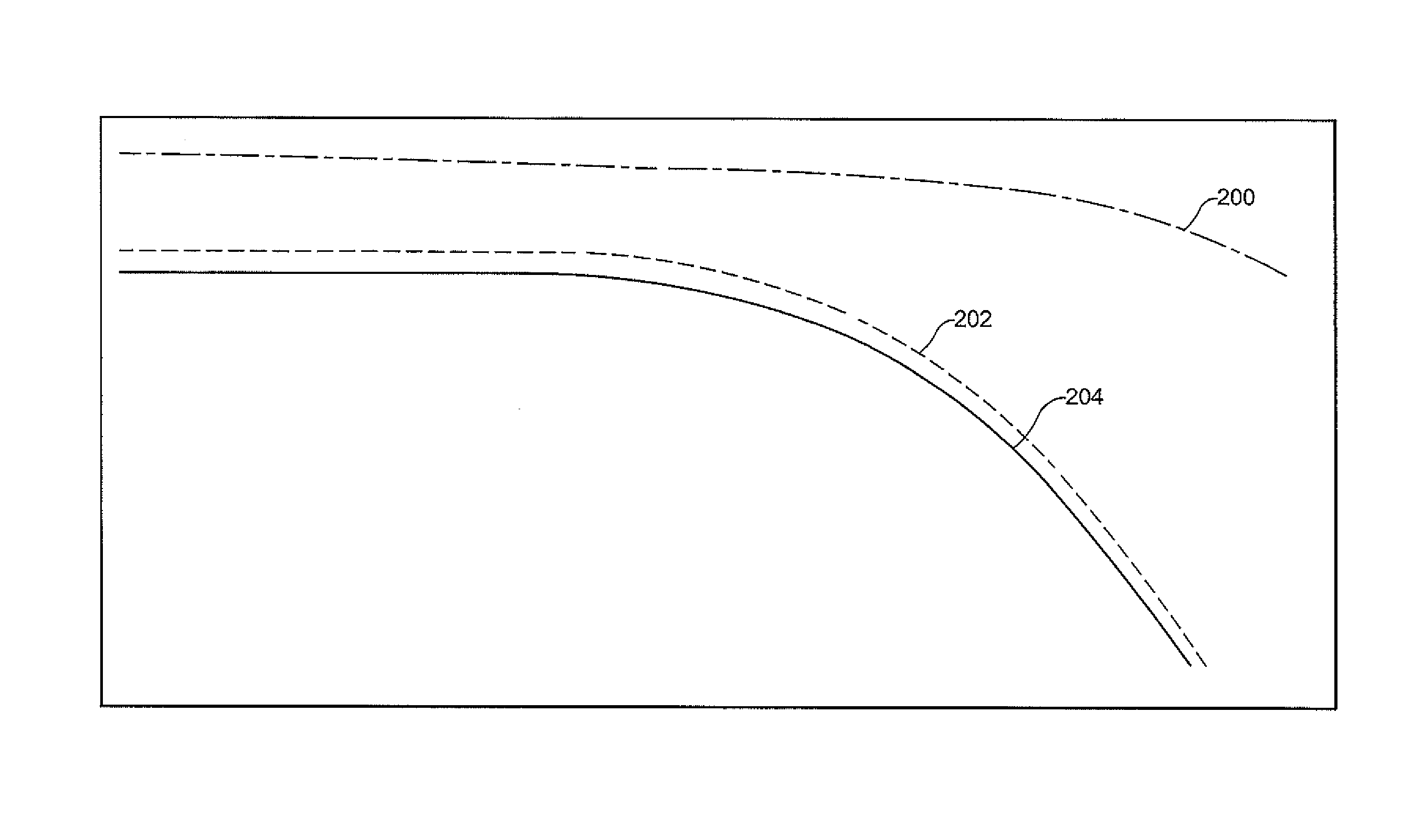
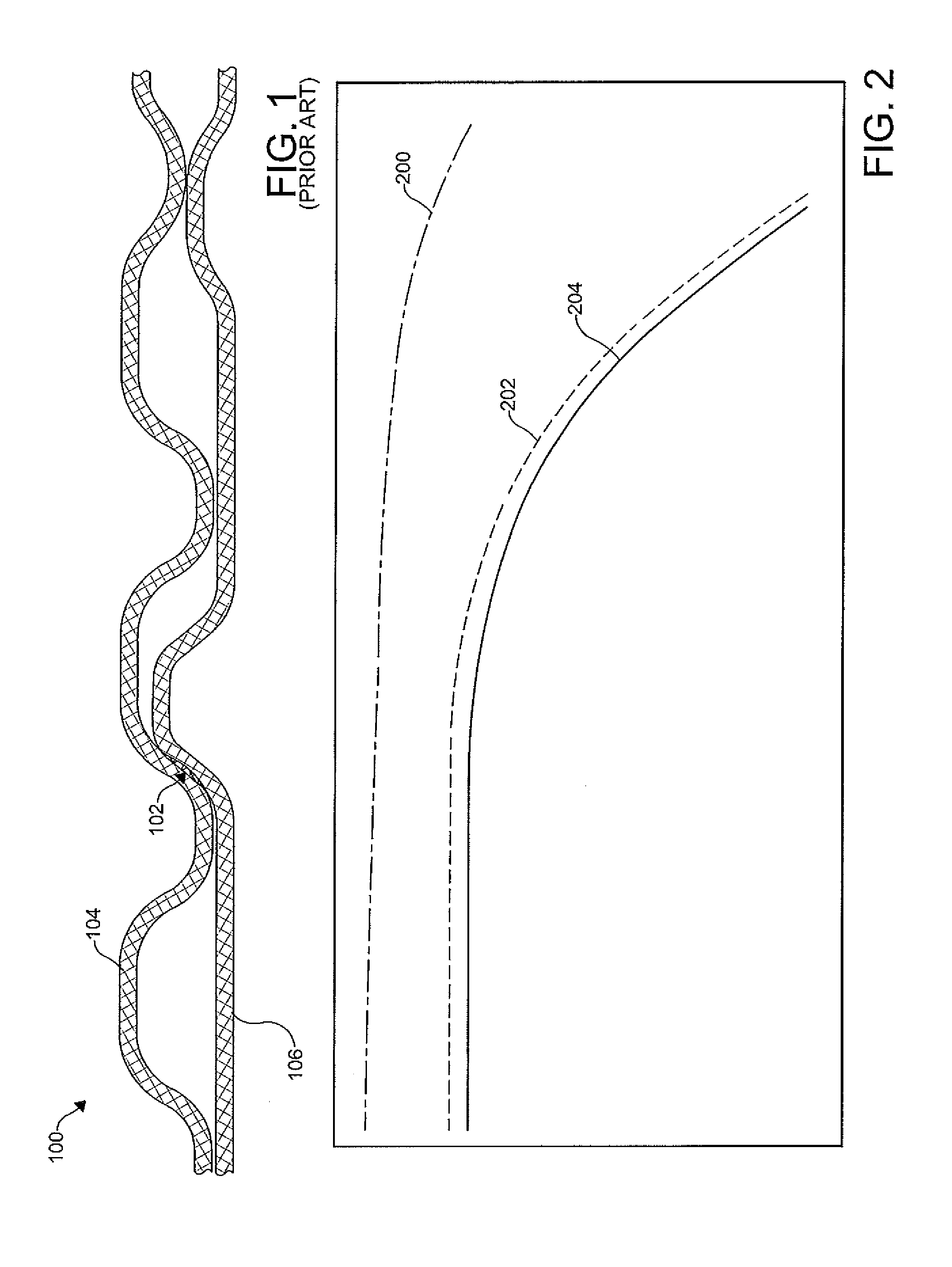
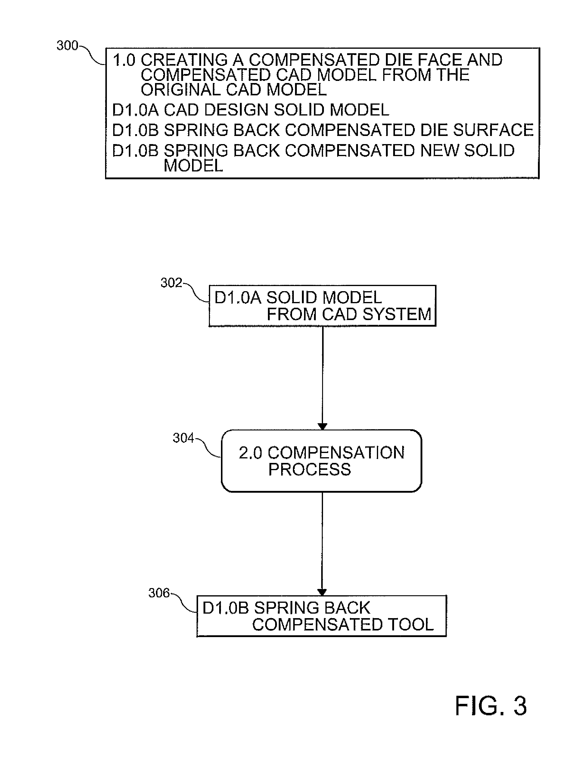
[0037]FIG. 2 schematically depicts a method for designing and manufacturing a stamped part according to the present disclosure. Although the stamped part is described largely herein as a bipolar plate for a fuel cell stack, it should be appreciated that the method of the present disclosure is also applicable to other stamped parts exhibiting spring back. The method first includes providing an original model of the stamped part, for example, identified by an original surface 200. A compensation process is then applied to the original model. T...


PUM

PropertyMeasurementUnit
thicknessaaaaaaaaaa
depthaaaaaaaaaa
depthaaaaaaaaaa

Abstract

A method for manufacturing a stamped part, such as a bipolar plate for a fuel cell, includes the steps of: providing an original model of the bipolar plate; and performing a compensation process on the original model, the compensation process including a two step morphing process based upon a prediction of spring back. The two step morphing process provides a compensated model of the stamped part. A compensated die face may be created based on the compensated model of the stamped part. The stamped part manufactured with the compensated die face has spring back compensation.

Description

FIELD OF THE INVENTION[0001]This invention relates to stamped parts such as bipolar plates for fuel cell stacks and, more particularly, to a method for manufacturing stamped parts to compensate for spring back in the stamped parts.BACKGROUND OF THE INVENTION[0002]A fuel cell has been proposed as a clean, efficient and environmentally responsible power source for various applications. In particular, individual fuel cells can be stacked together in series to form a fuel cell stack capable of supplying a quantity of electricity sufficient to power an electric vehicle. The fuel cell stack has been identified as a potential alternative for a traditional internal-combustion engine used in modern vehicles.[0003]Fuel cells are electrochemical devices which combine a fuel such as hydrogen and an oxidant such as oxygen to produce electricity. The oxygen is typically supplied by an air stream. The hydrogen and oxygen combine to result in the formation of water. Other fuels can be used such as ...

Claims


Application Information

Patent Timeline
Patent Type & Authority Patents(United States)
IPC IPC(8): G06F19/00G06T17/00G06T15/00B23Q17/00B23P17/04G06F17/50H01M8/02
CPCH01M8/0206Y02E60/50Y10T29/49Y10T29/49758Y02P70/50
Inventor XU, SIGUANGLEBLANC, PAUL A.SPENCER, STEVEN J.FLY, GERALD W.
Owner GM GLOBAL TECH OPERATIONS LLC
Why Eureka
Try Eureka