Switching electromagnetic valve

A technology for switching solenoid valves and valve bodies, applied in valve details, valve devices, valve operation/release devices, etc., can solve the problems of slow power-off return, large pull-in voltage, etc. Fast return speed and accurate control of the effect of switching on and off

Active Publication Date: 2011-06-15
WUXI LONGSHENG TECH
View PDF8 Cites 8 Cited by
  • Summary
  • Abstract
  • Description
  • Claims
  • Application Information

AI Technical Summary

Problems solved by technology

[0002] On-off solenoid valves used in existing automobiles, such as figure 1 As shown, the static iron core 16 attracts the moving iron core 21 through the electromagnetic coil, and the seal 20 and the moving iron core 21 are assembled as a whole through interference fit. The suction force of the static iron core 16 must overcome the spring 18 and the vacuum source connecting pipe 19 The resultant force of the negative pressure formed by vacuuming can make the brake connecting pipe 17 and the vacuum source connecting pipe 19 communicate, and when the power is cut off, the moving iron core 21 is pushed back to the vacuum source connecting pipe only by the force of the spring 18 19. At this time, the air inlet pipe 15 is connected to the brake connecting pipe 17. This structure has the disadvantages of large pull-in voltage and slow return after power failure.

Method used


Image

  • Switching electromagnetic valve
  • Switching electromagnetic valve
  • Switching electromagnetic valve

Examples


Embodiment Construction

[0010] The present invention will be further described below in conjunction with accompanying drawing.

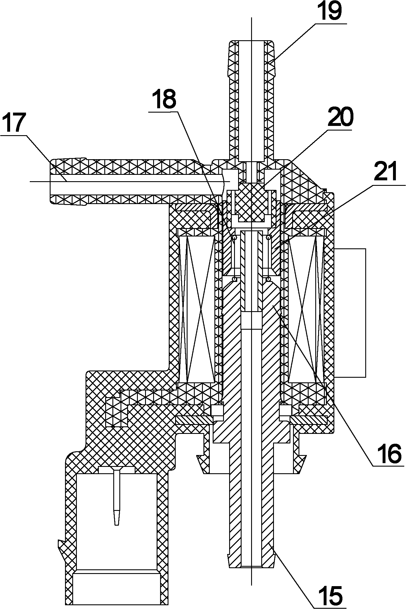
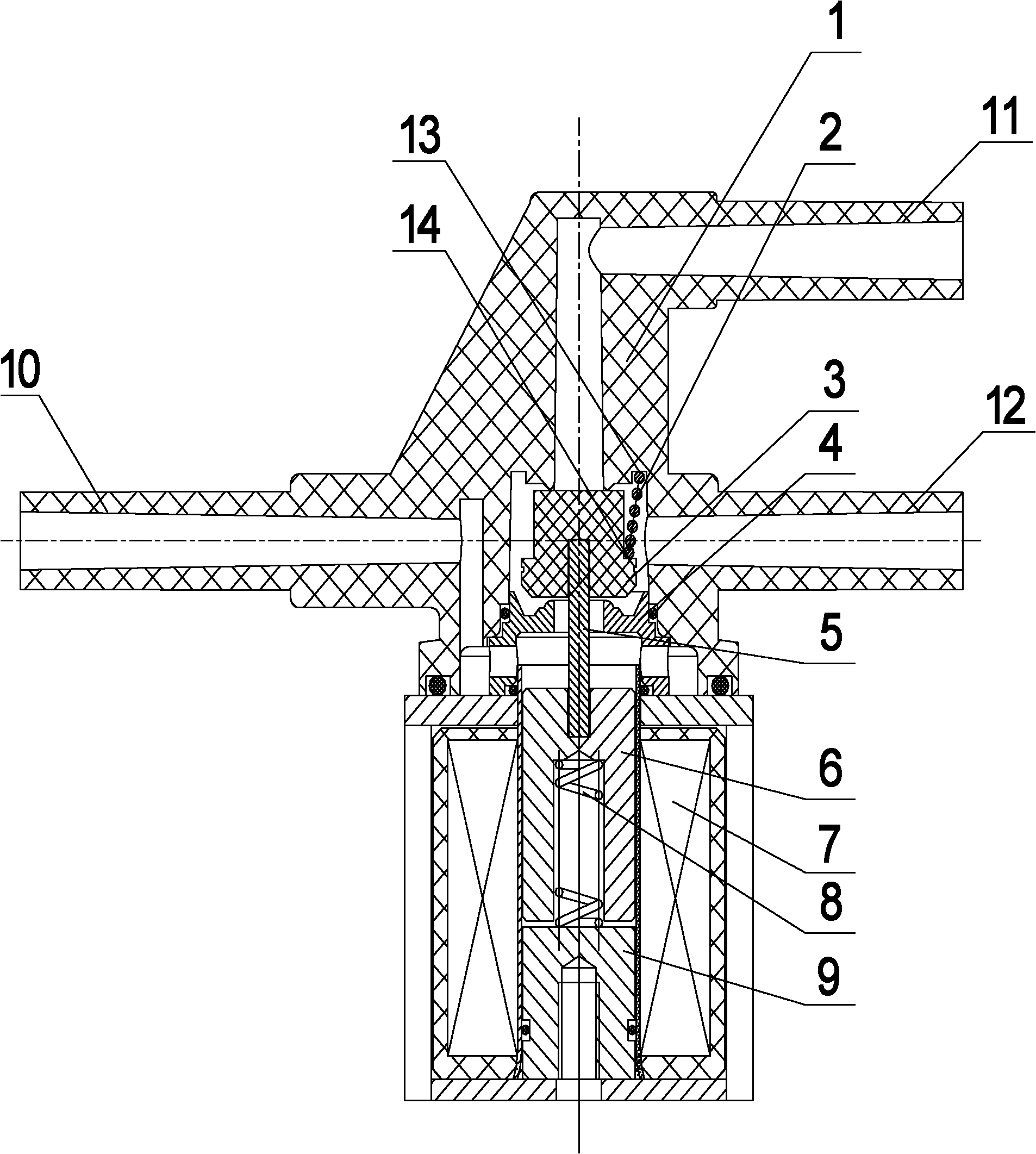
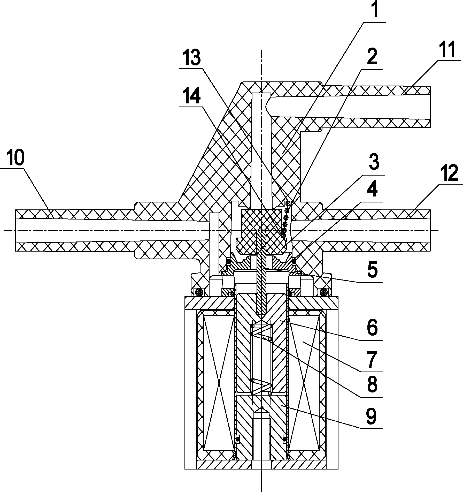
[0011] A switch solenoid valve, comprising a valve body 1, a static iron core 9, a moving iron core 6, and a coil 7 are arranged in the valve body 1, the static iron core 9 is arranged at the lower part of the valve body 1, and the moving iron core 6 is arranged in the valve body 1 Above the inner static iron core 9, an inner cavity is arranged on the end surface of the moving iron core 6 facing the static iron core 9, and a first spring 8 is arranged in the inner cavity, and a supporting rod is arranged on the other end surface of the moving iron core 6 5. A sealing cover 4 is set on the support rod 5, a top block 3 is set on the upper end of the support rod 5, a second spring 2 is set on the top block 3, a stepped surface 14 is set on the outer peripheral surface of the top block 3, One end surface of the second spring 2 is in contact with the stepped surface 14 , and the...


PUM


Abstract

The invention discloses a switching electromagnetic valve which comprises a valve body, wherein a static iron core, a moving iron core and a coil are arranged in the valve body; the static iron core is arranged at the lower part of the valve body; the moving iron core is above the static iron core in the valve body; the end surface of the moving iron core facing to the static iron core is provided with an inner cavity; a first spring is arranged in the inner cavity; the other end surface of the moving iron core is provided with a support rod; a sealing cover is sheathed on the support rod; the upper end of the support rod is provided with an ejection block; a second spring is sheathed on the ejection block; a step surface is arranged on the peripheral surface of the ejection block; one end surface of the second spring is in contact with the step surface, and the other end surface of the second spring is in contact with one inner end surface at the upper part of the valve body; and the elasticity of the first spring is greater than the elasticity of the second spring. Because the ejection block and the moving iron core are independent parts, the static iron core only needs to overcome the elasticity of the first spring and does not need to overcome the acting force which is formed by the negative pressure of a vacuum source on the ejection block; the actuation voltage is small; when the coil is switched off, the elasticity of the first spring is transferred to the ejection block through the moving iron core and the support rod; the ejection block is ejected to a vacuum source connecting pipe; the elasticity of the first spring is far larger than the elasticity of the second spring; the ejection block and the vacuum source connecting pipe can be rapidly abutted; the return speed is high; and the power-off return can be realized rapidly.

Description

technical field [0001] The invention relates to an on-off electromagnetic valve driven by an electromagnetic coil, which belongs to the field of on-off electromagnetic valves for automobiles. Background technique [0002] On-off solenoid valves used in existing automobiles, such as figure 1 As shown, the static iron core 16 attracts the moving iron core 21 through the electromagnetic coil, and the seal 20 and the moving iron core 21 are assembled as one through interference fit. The suction force of the static iron core 16 must overcome the spring 18 and the vacuum source connecting pipe 19 The combined force of the negative pressure formed by vacuuming can make the brake connecting pipe 17 and the vacuum source connecting pipe 19 communicate, and when the power is cut off, the moving iron core 21 is pushed back to the vacuum source connecting pipe only by the force of the spring 18 19. At this time, the air inlet pipe 15 is connected to the brake connecting pipe 17. This s...

Claims


Application Information

Patent Timeline
Patent Type & Authority Applications(China)
IPC IPC(8): F16K31/06
Inventor 陈凯倪铭张华肖琳都兴鹏
Owner WUXI LONGSHENG TECH
Why Eureka
Try Eureka