Water pressure application device for prototype test of push shield tunnel structure

A technology for structural prototypes and shield tunnels, which is applied in the testing of machines/structural components, measuring devices, instruments, etc., and can solve problems such as affecting test results, breaking hoop anchor cables, and existing safety hazards

Active Publication Date: 2016-02-03
SOUTHWEST JIAOTONG UNIV
View PDF6 Cites 0 Cited by
  • Summary
  • Abstract
  • Description
  • Claims
  • Application Information

AI Technical Summary

Problems solved by technology

There is a large tension gap in the left and right areas of the hoop beam, and additional concentrated force is generated at the hoop beam. When the simulated water pressure is large, the effect of the additional concentrated force at the hoop beam is very significant, which seriously affects the test results.
[0004] Secondly, the hoop anchor cable forms an inflection point at the edge A of the anchor cable hole, and the stress is concentrated here during tension, which will cause the hoop anchor cable to break easily here, posing a safety hazard

Method used


Image

  • Water pressure application device for prototype test of push shield tunnel structure
  • Water pressure application device for prototype test of push shield tunnel structure
  • Water pressure application device for prototype test of push shield tunnel structure

Examples


specific Embodiment approach

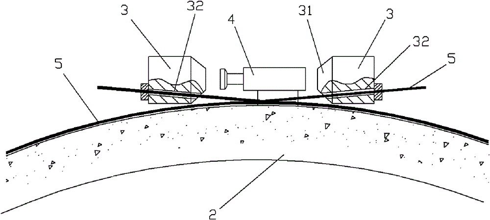
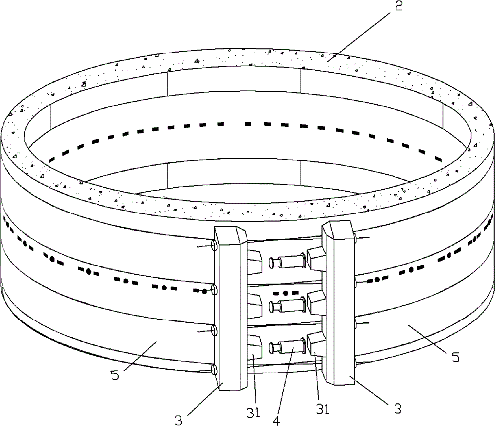
[0018] Figure 1-2 Shown, a kind of specific embodiment of the present invention is:

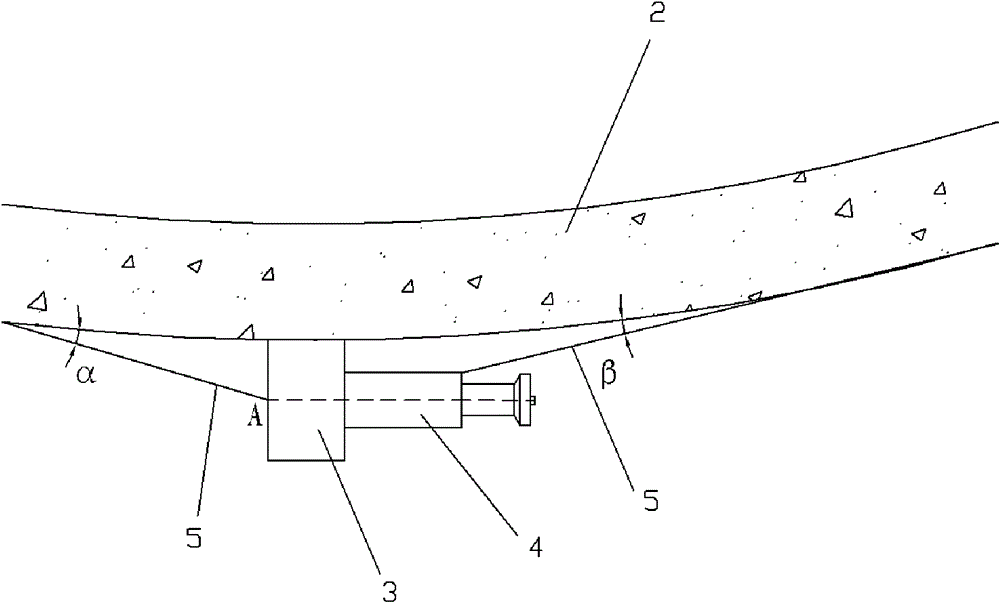
[0019] A jacking type shield tunnel structure prototype test hydraulic pressure application device, which is composed of: the top of the tunnel structure prototype 2 whose central axis is parallel to the ground is provided with more than two circumferential jacks 4, and the two ends of the jacks 4 are respectively There are longitudinal left and right push beams 3; the hoop anchor cable 5 circles the surface of the tunnel structure prototype 2 and intersects on the top surface of the tunnel structure prototype 2 between the left and right push beams 3. After crossing, the two The ends are respectively connected with the left and right push beam bodies 3. The opposite sides of the left and right push beam bodies 3 are respectively equipped with push force transmission bodies 31, and jacks 4 are arranged between the push force transmission bodies 31.

[0020] The left and right push beams 3 ...


PUM


Abstract

The invention discloses a pushing-type tested hydraulic pressure application device for a shield tunnel structure prototype, which is formed by that the top of a tunnel structure prototype (2) of which the central axis is parallel to the ground is provided with more than two circumferential jacks (4); two ends of each jack (4) are respectively provided with a longitudinal left pushing beam body (3) and a longitudinal right pushing beam body (3); two ends of a hoop anchor rope (5) are intersected on the top surface of the tunnel structure prototype (2) between the longitudinal left pushing beam body (3) and the longitudinal right pushing beam body (3) after the hoop anchor rope (5) surrounds the surface of the tunnel structure prototype (2) for one circle; and two interacted ends are respectively connected with the longitudinal left pushing beam body (3) and the longitudinal right pushing beam body (3). According to the device, interference on structure hydraulic pressure simulation because of additional concentrated force on the hoop beam in a self-anchoring hoop method, so that the action and the influence on the prototype tunnel structure by the environmental hydraulic pressure can be truly simulated, more accurate and reliable test basis is provided for the design and the construction of underwater shield tunnel structure, and the tunnel can be safely built and operated.

Description

technical field [0001] The invention relates to a shield tunnel segment structure prototype test device, in particular to a push-type shield tunnel structure prototype test water pressure application device. Background technique [0002] The application of water pressure to the shield tunnel prototype segment structure is usually realized by a self-anchoring hoop device. The schematic diagram of the partial structure in the top view is shown in image 3 . Its composition is: the shield tunnel structure prototype 2 is placed vertically on the ground (its central axis is perpendicular to the ground), two hoop beams 3 are longitudinally arranged on the outer peripheral surface, a jack 4 is arranged on one side of the hoop beam 3, and the hoop The beginning end of the anchor cable 5 passes through the anchor cable hole at the beginning end of the hoop beam 3, and then circles around the prototype 2 of the shield tunnel structure, and then the end passes through the end anchor ca...

Claims


Application Information

Patent Timeline
Patent Type & Authority Patents(China)
IPC IPC(8): G01M99/00
Inventor 何川封坤汪波
Owner SOUTHWEST JIAOTONG UNIV
Why Eureka
Try Eureka