Supercharge Your Innovation With Domain-Expert AI Agents!

Magnetic recording disk and disk drive having track markings using phase-type servo patterns

A magnetic recording, pattern technology, applied in the direction of pattern record carrier, magnetic recording, different record carrier forms, etc.

Inactive Publication Date: 2015-11-18
WESTERN DIGITAL TECH INC
View PDF5 Cites 0 Cited by
  • Summary
  • Abstract
  • Description
  • Claims
  • Application Information

AI Technical Summary

Problems solved by technology

However, conventional phase-type servo patterns of this type still require a separate track identification (TID) field (typically a Gray code pattern) that must be read and decoded in order to determine the absolute position of the read head

Method used


Image

  • Magnetic recording disk and disk drive having track markings using phase-type servo patterns
  • Magnetic recording disk and disk drive having track markings using phase-type servo patterns
  • Magnetic recording disk and disk drive having track markings using phase-type servo patterns

Examples


Embodiment Construction

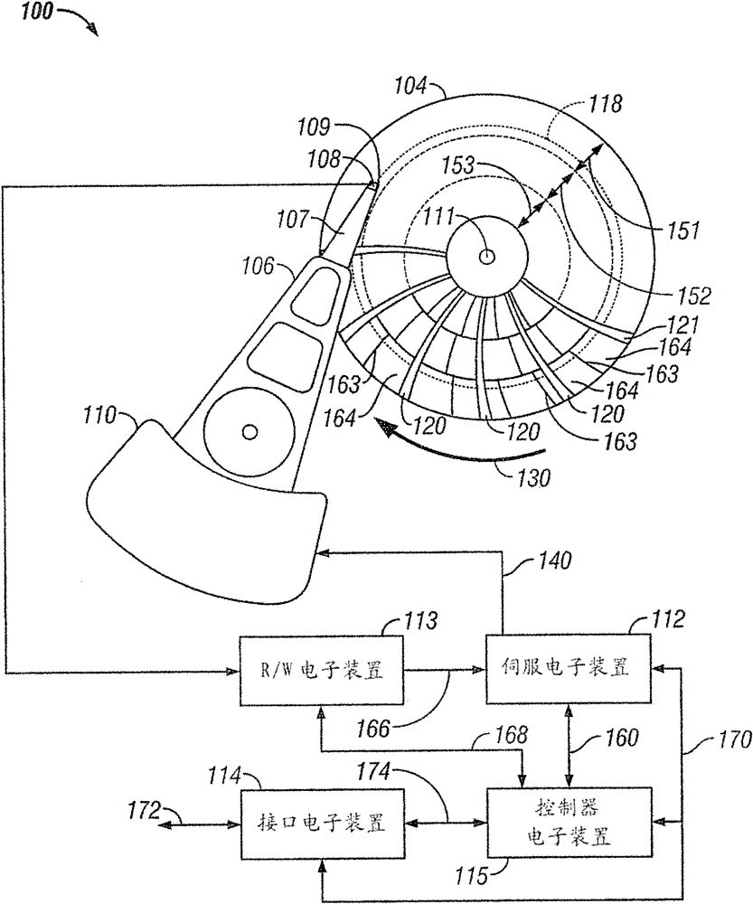
[0025] figure 1 is a schematic diagram of a conventional magnetic recording disk drive and illustrates a non-data area (specifically, a servo sector for positioning the recording head on a data track) and a sync field for enabling the recording head to be in the data sector read and write data) magnetic recording disk. A disk drive, generally designated 100 , includes a magnetic recording disk 104 , a voice coil motor (VCM) actuator 110 , an actuator arm 106 , a suspension 107 , a head carrier or air bearing slider 108 , and a recording head 109 . The recording head 109 is typically a combination of an inductive write head and a magnetoresistive read head (also referred to as a read / write head), and is located on the trailing or end face of the slider 108 . Suspension 107 supports slider 108 on actuator arm 106, wherein suspension 107 enables the slider to "pitch" and "roll" on the air cushion created when disk 104 rotates in the direction of arrow 130. )". figure 1 Only on...


PUM


Abstract

A magnetic recording disk drive has a disk with a head positioning servo pattern of multiple circumferentially-spaced chevron patterns of discrete patterned servo islands. The disk drive has servo electronics that decodes the chevron patterns to determine the absolute radial position of the head without the need for separate track identification fields. The chevron pattern with the smallest radial period has a radial period P1 and each of the other chevron patterns has a period which is a unique multiple of P1. In one embodiment the first chevron pattern read by the head has period P1 and each successive chevron pattern read by the head has a period that is greater than the period of the chevron pattern immediately preceding it such that the period of each chevron pattern progressively increases.

Description

technical field [0001] This invention relates generally to magnetic recording disks comprising patterned media disks storing each bit of data in magnetically isolated data islands on the disk, and more particularly to magnetic recording disks having patterned phase-type servo patterns for head positioning disks and disk drives. Background technique [0002] Conventional magnetic recording disk drives use disks with "continuous" media, meaning that the magnetic recording layer is a continuous film of magnetizable material. In conventional continuous media disks, concentric data tracks are not physically separated from each other and are not pre-formed in the recording layer, but are formed when a write field from a write head creates magnetization in the continuous magnetic layer. Continuous media disks may also be "discrete-track" disks, meaning that concentric data tracks of continuous magnetic material are radially separated from each other by concentric nonmagnetic guard...

Claims


Application Information

Patent Timeline
Patent Type & Authority Patents(China)
IPC IPC(8): G11B5/82G11B5/66
CPCG11B5/855B82Y10/00G11B5/59655G11B5/743G11B5/746G11B5/82
Inventor 布鲁斯.A.威尔逊
Owner WESTERN DIGITAL TECH INC
Features
  • R&D
  • Intellectual Property
  • Life Sciences
  • Materials
  • Tech Scout
  • Unparalleled Data Quality
  • Higher Quality Content
  • 60% Fewer Hallucinations
Learn More