Method and apparatus for absolute track spacing determination for self-servowriting

a self-servowriting and absolute track technology, applied in the field of methods, can solve the problems of insufficient traditional servowriting methods, inability to disclose the method of determining absolute track spacing, and becoming more and more difficult for such servowriters to invade the internal environment of the hda for servowriting

Inactive Publication Date: 2002-02-05
HITACHI GLOBAL STORAGE TECH NETHERLANDS BV
View PDF12 Cites 62 Cited by
  • Summary
  • Abstract
  • Description
  • Claims
  • Application Information

AI Technical Summary

Problems solved by technology

However, when track densities are so great that the mechanical error of a lead screw-stepper motor combination is significant compared to track-to-track spacing, an embedded servo is needed so that the position of the head can be determined from the signals it reads.
Unfortunately, it is becoming more and more difficult for such servowriters to invade the internal environment of a HDA for servowriting because the HDAs themselves are exceedingly small and depend on their covers and castings to be in place for proper operation.
At such levels of micro miniaturization, traditional servowriting methods are inadequate.
Unfortunately, Oliver et al. does not disclose how to determine absolute spacing without first servo writing the entire hard disk surface.
A shortcoming of the some prior techniques is the lesser accuracy in placement of the servo patterns.
This makes detection more difficult, and can lead to disk damage if the heads are only partially lifted off the disk.

Method used


Image

  • Method and apparatus for absolute track spacing determination for self-servowriting
  • Method and apparatus for absolute track spacing determination for self-servowriting
  • Method and apparatus for absolute track spacing determination for self-servowriting

Examples


second embodiment

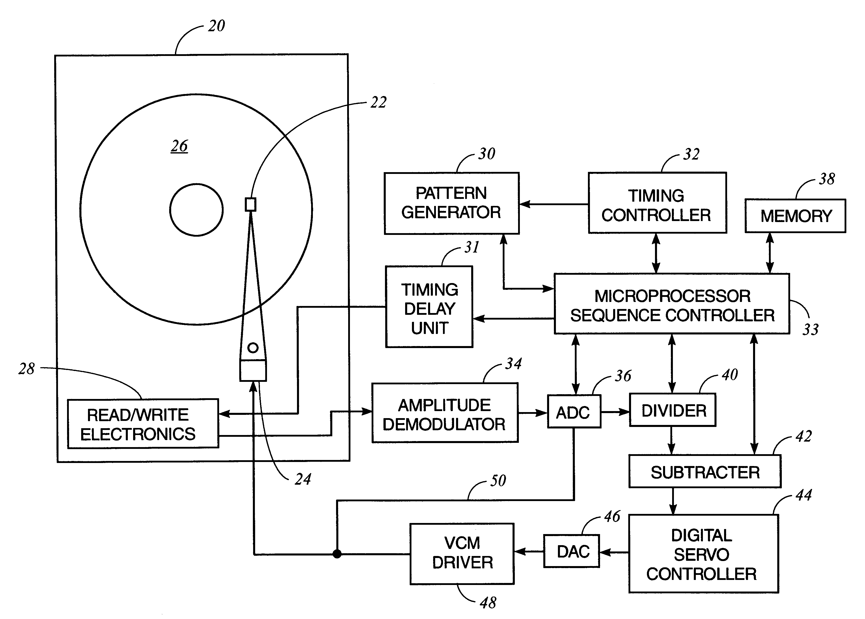
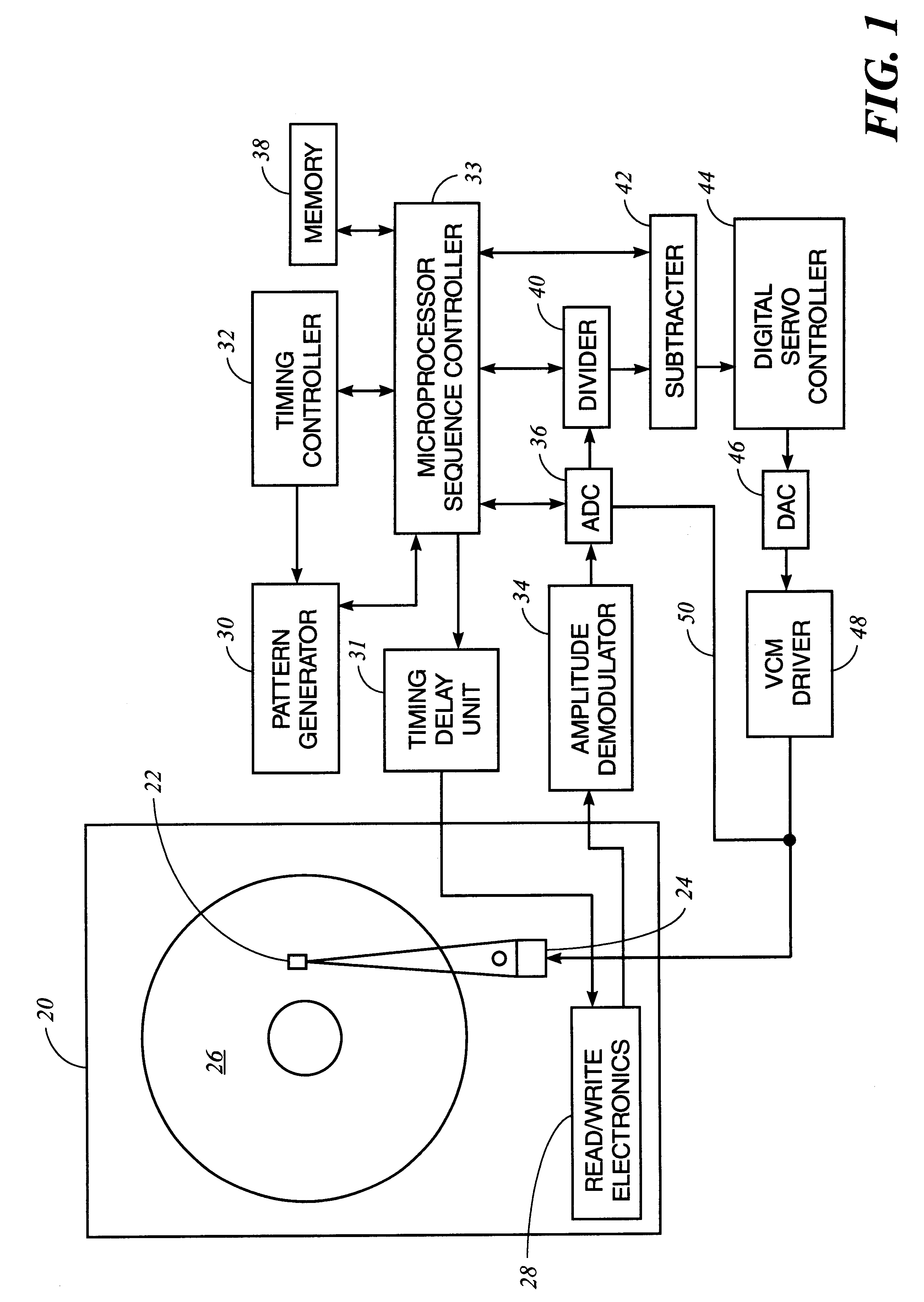
In the self-servowriter, the nominal average reference level is iteratively adjusted using measurements of the gap between tracks (physically separate read and write section and FIGS. 5 & 6), as indicated by the relative amplitude at the midpoint between tracks. In this case, a desired relative amplitude is chosen that is approximately correct for most recording heads, the test tracks are written, the absolute spacing measured, and the adjustment will be applied to the relative amplitude since it controls the actual track spacing. The product patterns will then be written using the adjusted relative amplitude parameter.

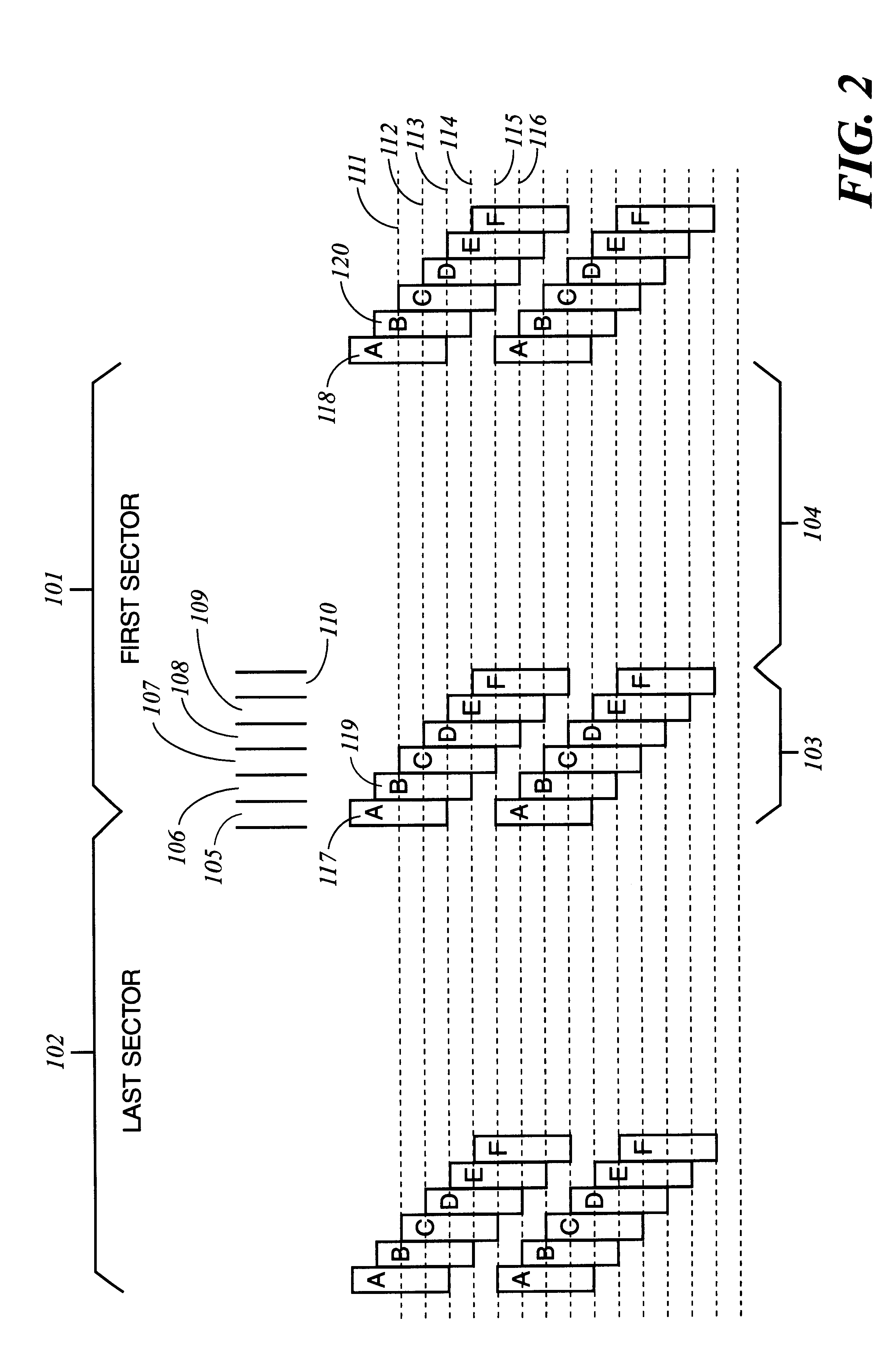
The principle of the spacing measurement is as follows. The uniformly spaced tracks provide a "ruler" which are used for measurements of dynamical quantities such as angular acceleration of the actuator arm. Imposing an absolute angular acceleration of the arm by applying a known amount of current to the voice coil motor (VCM) of the actuator calibrates the "ruler" pr...


PUM

PropertyMeasurementUnit
slot timeaaaaaaaaaa
currentaaaaaaaaaa
torque constantaaaaaaaaaa

Abstract

A method and apparatus to determine and correct track spacing during self-servowriting on a rotating recording medium. The recording medium comprising a plurality of tracks, wherein each track comprises a plurality of sectors, and a transducer mounted on an actuator arm pivotally coupled to a voice coil motor (VCM). The actuator arm is positioned by a servo. The method comprising the steps of: servowriting the at least one of the plurality of sectors with a servo pattern consisting of recorded transitions. The servowriting is performed on one more tracks within the sectors where the number of tracks being servowritten is less than total number of tracks that fills the rotating medium. The transducer is positioned relative to the rotating recording medium to a preselected radial position over a previously servowritten area of the rotating recording medium that has one or more previously recorded transitions. Next, an angular acceleration is imposed on the actuator arm by applying a predetermined amount of current to the VCM. The measurement and correction of a spacing of the tracks in the previously servowritten area is performed by measuring the amplitudes of the previously recorded transitions at least one time during the passage of the sectors beneath the transducer, and if the calibratng of the spacing is outside a predetermined tolerance, then continuing servowriting new recorded transitions using said adjustment factor on tracks following said previously servowritten area. In one embodiment, the method includes measuring a VCM torque constant (K) by applying a current impulse for a predetermined time (t) and measuring the back Electromotive Force (EMF) generated from the VCM to determine the torque per unit for the current impulse for the predetermined time (t) and to determine the back Electronic Force (EMF) per unit of angular velocity of the actuator arm. After the torque constant is determined, an adjustment factor is computed based on the values of the torque constant (K), the current impulse for the period of time (t), and the back Electromotive Force (EMF)per unit of angular velocity of the actuator arm. This adjustment factor is used while servowriting now recorded transitions tacks following the previously servowritten area.

Description

Not applicable1. Field of the InventionThis invention relates generally to hard disk drive memory storage devices and more particularly to a method and apparatus for determining and correcting the absolute track spacing without having to traverse across the entire disk surface.2. Description of the Related ArtAs described in International Patent Application, WO 94 / 11864, high track densities are possible with voice-coil and other types of servo positioners as well as the ability to read and write narrower tracks by using, for example, magneto resistive (MR) head technology. Previously, low track density disk drives were able to achieve satisfactory head positioning with lead screw and stepper motor mechanisms. However, when track densities are so great that the mechanical error of a lead screw-stepper motor combination is significant compared to track-to-track spacing, an embedded servo is needed so that the position of the head can be determined from the signals it reads.Convention...

Claims


Application Information

Patent Timeline
Patent Type & Authority Patents(United States)
IPC IPC(8): G11B5/596G11B5/55
CPCG11B5/59633G11B5/5534
Inventor YARMCHUK, EDWARD JOHN
Owner HITACHI GLOBAL STORAGE TECH NETHERLANDS BV
Why Eureka
Try Eureka