Fixed cutter bit with backup cutter elements on primary blades

a technology of primary blades and cutter elements, applied in the field of drill bits, can solve the problems of reducing or preventing the penetration of the cutting structure, reducing the cutting rate, and potentially increasing the wear of the cutting surfa

Inactive Publication Date: 2010-04-27
SMITH INT INC
View PDF99 Cites 60 Cited by
  • Summary
  • Abstract
  • Description
  • Claims
  • Application Information

AI Technical Summary

Problems solved by technology

Otherwise, accumulation of formation materials on the cutting structure may reduce or prevent the penetration of the cutting structure into the formation.
Failure to remove formation materials from the bottom of the hole may result in subsequent passes by cutting structure to re-cut the same materials, thus reducing cutting rate and potentially increasing wear on the cutting surfaces.
Thus, the number and placement of drilling fluid nozzles, and the resulting flow of drilling fluid, may significantly impact the performance of the drill bit.
Without regard to the type of bit, the cost of drilling a borehole for recovery of hydrocarbons may be very high, and is proportional to the length of time it takes to drill to the desired depth and location.
As is thus obvious, this process, known as a “trip” of the drill string, requires considerable time, effort and expense.
In addition, the greater the number of relatively long primary blades extending along the bit face, the less space is available for the placement of drilling fluid nozzles.
Space limitations may result in the placement of fluid nozzles in less desirable locations about the bit.
Compromised nozzle placement may also detrimentally impact fluid hydraulic performance, bit ROP, and bit durability.
Still further, space limitations for fluid nozzles may result in more complex bit designs necessary to accommodate drilling fluid channels and nozzles.
The increased complexity in the design and manufacture of the bit may increase bit costs.
A reduction in the total number of cutter elements may detrimentally lower the ROP of the bit.

Method used


Image

  • Fixed cutter bit with backup cutter elements on primary blades
  • Fixed cutter bit with backup cutter elements on primary blades
  • Fixed cutter bit with backup cutter elements on primary blades

Examples


Embodiment Construction

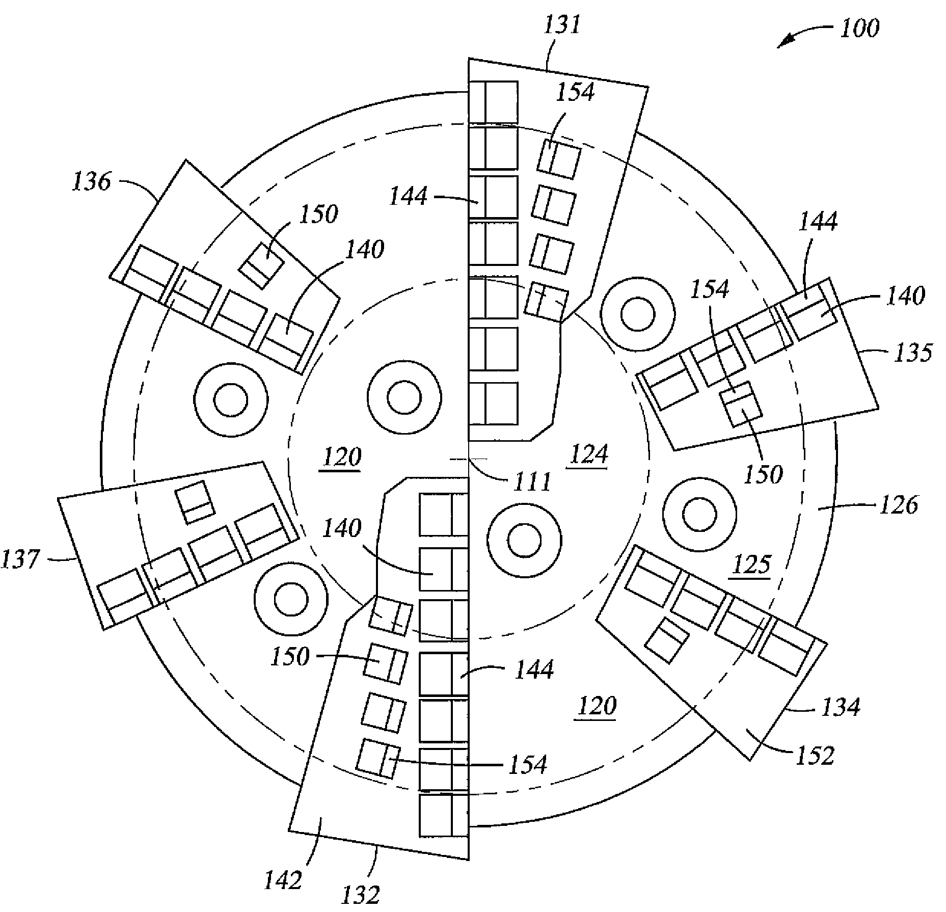
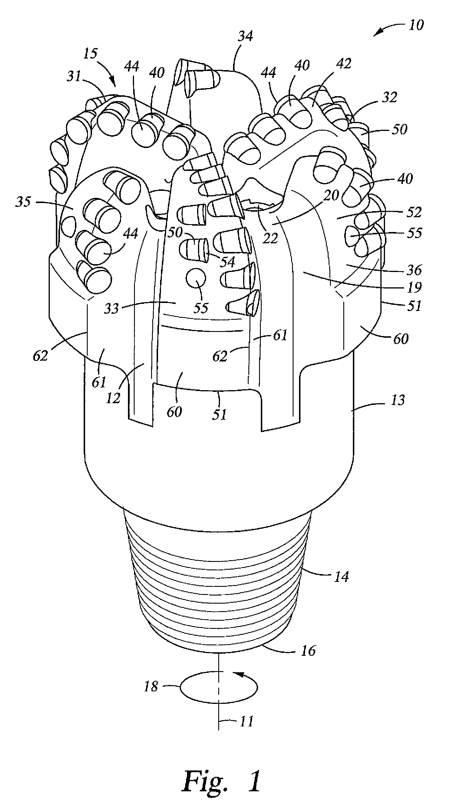
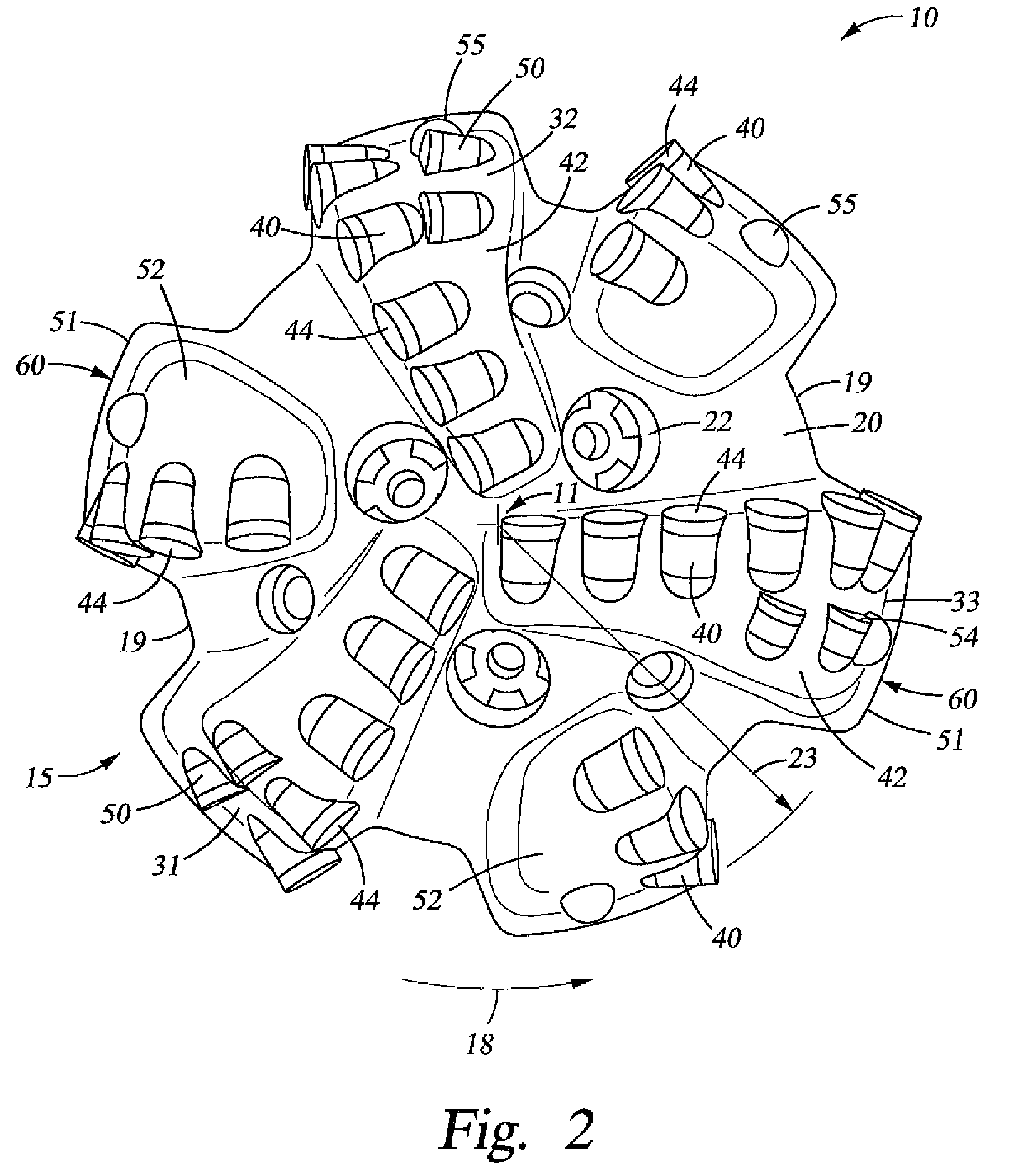
[0015]In accordance with at least one embodiment of the invention, a drill bit for drilling a borehole in earthen formations comprises a bit body having a bit face including a cone region, a shoulder region, and a gage region. In addition, the drill bit comprises a primary blade extending radially along the bit face from the cone region through the shoulder region to the gage region. Further, the drill bit comprises a plurality of primary cutter elements mounted to the primary blade. Still further, the drill bit comprises at least one backup cutter element mounted to the primary blade in the shoulder region. Moreover, the drill bit comprises a secondary blade extending along the bit face from the shoulder region to the gage region. In addition, the drill bit comprises a plurality of primary cutter elements mounted to the secondary blade. The secondary blade is free of backup cutter elements. Each backup cutter element mounted to the primary blade is disposed at substantially the sam...


PUM


Abstract

A drill bit for drilling a borehole comprises a bit body having a bit face. In addition, the drill bit comprises a plurality of primary blades. Further, the drill bit comprises a plurality of primary cutter elements mounted to each primary blade and at least one backup cutter element mounted to each primary blade. Still further, the drill bit comprises a plurality of secondary blades. Moreover, the drill bit comprises a plurality of primary cutter elements mounted to each secondary blade. The ratio of the total number of backup cutter elements mounted to the plurality of primary blades to the total number of backup cutter elements mounted to the plurality of secondary blades is greater than 2.0. Each backup cutter element on each primary blade has substantially the same radial position as one of the primary cutter elements on the same primary blade.

Description

CROSS-REFERENCE TO RELATED APPLICATIONS[0001]Not Applicable.STATEMENT REGARDING FEDERALLY SPONSORED RESEARCH OR DEVELOPMENT[0002]Not Applicable.BACKGROUND[0003]1. Field of the Invention[0004]The invention relates generally to earth-boring drill bits used to drill a borehole for the ultimate recovery of oil, gas, or minerals. More particularly, the invention relates to drag bits and to an improved cutting structure for such bits. Still more particularly, the present invention relates to drag bits with backup cutters on primary blades.[0005]2. Background of the Invention[0006]An earth-boring drill bit is typically mounted on the lower end of a drill string and is rotated by rotating the drill string at the surface or by actuation of downhole motors or turbines, or by both methods. With weight applied to the drill string, the rotating drill bit engages the earthen formation and proceeds to form a borehole along a predetermined path toward a target zone. The borehole thus created will h...

Claims


Application Information

Patent Timeline
Patent Type & Authority Patents(United States)
IPC IPC(8): E21B10/43
CPCE21B10/43
Inventor DURAIRAJAN, BALAHOFFMASTER, CARL M.DOUGLAS, III, CHARLES H. S.CISNEROS, DENNIS
Owner SMITH INT INC
Why Eureka
Try Eureka