An intelligent battery management system

A management system and intelligent battery technology, applied in battery circuit devices, current collectors, electric vehicles, etc., can solve problems such as waste and energy consumption, and achieve the effect of balancing differences, prolonging service life, and ensuring safety

Active Publication Date: 2015-08-19
能际动力科技(苏州)有限公司
View PDF4 Cites 0 Cited by
  • Summary
  • Abstract
  • Description
  • Claims
  • Application Information

AI Technical Summary

Problems solved by technology

However, due to the secondary charging of the battery, the balanced management of the battery inevitably produces energy consumption, resulting in waste

Method used


Image

  • An intelligent battery management system
  • An intelligent battery management system
  • An intelligent battery management system

Examples


Embodiment 1

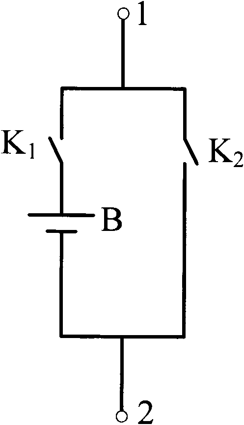
[0042] Figure 5 It is a schematic diagram of the system structure of this embodiment. Such as Figure 5 As shown, 100 is the basic unit, 200 is the slave control module, and 300 is the master control module. The basic unit 100 adopts the first type of basic unit. The intelligent battery management system includes multiple basic units 100, slave control modules 200, and a master control module 300; the slave control modules 200 regularly detect the voltage and current of the battery in the corresponding basic unit 100 through current sensors, voltage sensors, and temperature sensors , temperature and these states, and transmit the detection data to the MCU in the slave control module 200, and the MCU transmits the data to the MCU in the main control module 300 through wireless communication Zigbee, and the MCU in the main control module 300 stores The received information will display the SOC of the battery on the LCD, whether there is a fault, etc., and the MCU judges the ...

Embodiment 2

[0047]This embodiment is similar to the first embodiment, except that a current sensor and a thermistor are used to detect the battery in the basic unit, and an STC89C52 is used as the MCU. The chip has no built-in ADC and RF communication, and needs to be added externally. The model used by the ADC is ADC0809CCN, which is an 8-bit ADC with a measurement accuracy of 20mv at a reference voltage of 5V, and has 8 optional signal inputs; the RF communication uses ZigBee. The current sensor can be a Hall sensor, MR sensor, AMR, GMR, or TMR sensor. In this embodiment, a Hall ACS755LCB-050 is used, and the output signal is a voltage signal. Figure 8 It is a schematic circuit diagram of a basic unit and a slave control module of this embodiment. As shown in the figure, R 2 is a fixed resistor, R T It is a thermistor. When the temperature changes, the resistance of the thermistor changes, and the Vt obtained by dividing the voltage also changes. The signal V of the three analog se...

Embodiment 3

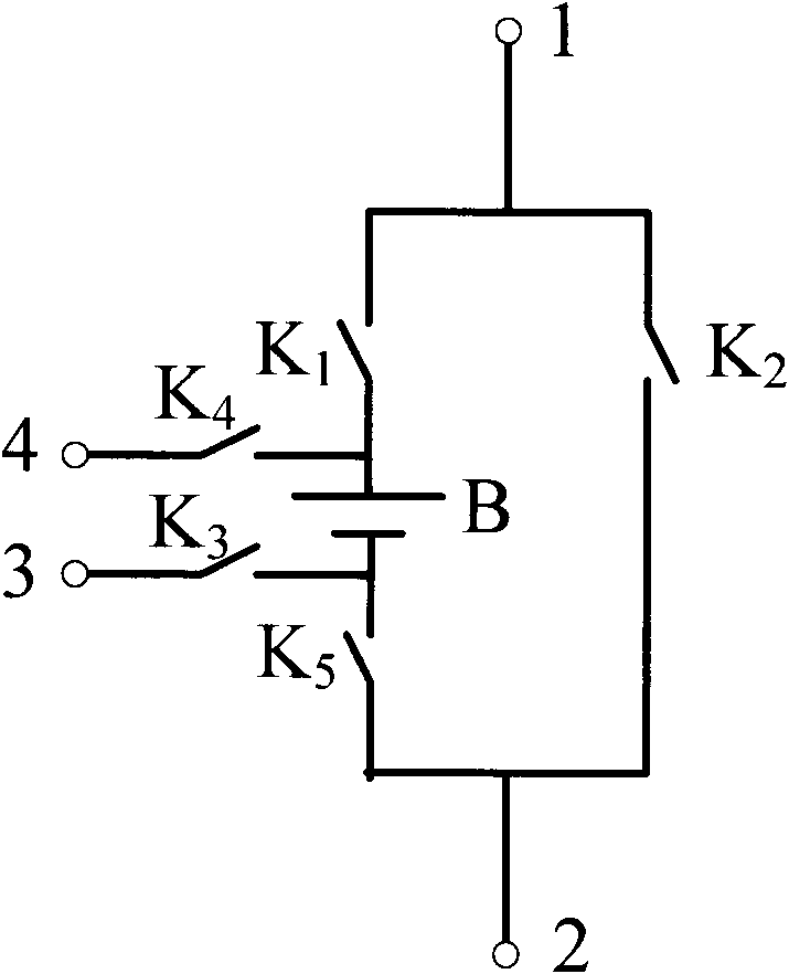
[0049] This embodiment is similar to the first embodiment, except that the second basic unit is used. The switch is a relay, and the battery is a nickel metal hydride battery. Since the second basic unit is used, the system can be charged in the same way as in the first embodiment when the system is in the charging state, or the batteries in each basic unit can be connected in parallel to realize parallel charging. The system is the same as that of embodiment 1 in the discharge state.


PUM


Abstract

The invention discloses an intelligent battery management system which comprises a plurality of basic units, slave control modules and a master control module, wherein the slave control modules are used for detecting the states of batteries in the corresponding basic units at regular time and transmitting the detection data to MCUs (Microprogrammed Control Units) in the slave control modules, the MCUs of the slave control modules transmit the detection data to the MCU in the master control module, the MCU in the master control module judges the state of each battery according to the received information, correspondingly controls each battery and transmits a control instruction to the MCUs in the slave control modules, and the MCUs in the slave control modules execute the instruction. The intelligent battery management system enables each battery to evenly discharge and to be fully charged in the charging process, thereby eliminating the short-board phenomenon, prolonging the service life of each battery, increasing the energy efficiency of each battery and improving the operation reliability of the system.

Description

technical field [0001] The invention relates to an intelligent battery management system, in particular to an intelligent battery management system capable of uniformly discharging each battery and fully charging it. Background technique [0002] The rapid development of China's transportation industry is putting more and more pressure on the environment, and the number of cars on the road in the country is increasing at a rate of 10 million per year. Exhaust gas emitted by ordinary cars has become a source of air pollution that cannot be ignored. [0003] Electric vehicles replace oil with electricity and can achieve "zero emissions", which is an important means to solve energy and environmental problems. With the shortage of oil resources and the development of battery technology, electric vehicles are close to or even superior to traditional fuel vehicles in terms of performance and economy, and have begun to be gradually promoted and applied worldwide. [0004] At pres...

Claims


Application Information

Patent Timeline
Patent Type & Authority Patents(China)
IPC IPC(8): H02J7/00
Inventor 余维
Owner 能际动力科技(苏州)有限公司
Why Eureka
Try Eureka