Method and device for controlling multiple safety protection and energy-saving charging
A technology of safety protection and control methods, applied in emergency protection circuit devices, circuit devices, battery circuit devices, etc., can solve the problems of expensive batteries, prominent energy-saving problems, and inevitable contact with the human body.
- Summary
- Abstract
- Description
- Claims
- Application Information
AI Technical Summary
Problems solved by technology
Method used
Image
Examples
Embodiment 1
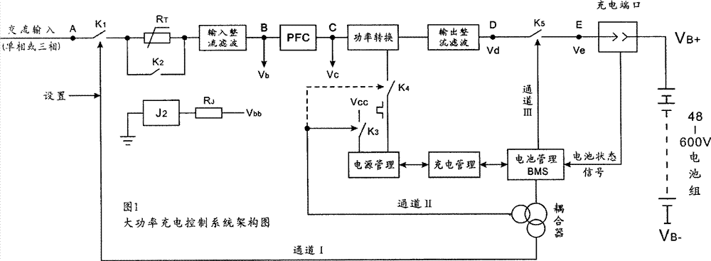
[0033] Such as figure 1 As shown, the multiple safety protection and energy-saving charging control method of the present invention includes the following steps:
[0034] 1) Prepare an AC input terminal, start current limiting resistor RT, input rectification filter circuit, input PFC circuit, power conversion circuit, power management circuit BMS, output rectification filter circuit, charging management circuit, battery management circuit, coupling feedback circuit, Charging port and battery pack;
[0035] 2) Between the AC input terminal and the start-up current limiting resistor, between the power management circuit and the supply power management circuit, between the power conversion circuit and the power management circuit, between the voltage terminals between the output rectification filter circuit and the charging port, respectively set One controllable switching device K1, K3, K4, K5, and one controllable switching device K2 is connected in parallel with the starting...
Embodiment 2
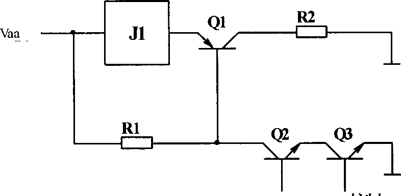
[0051] As shown in 3-2, the conduction switch Q1 in the control switch K1 can be replaced by a P-MOS transistor.
[0052] Or the conduction switch Q1 in the control switch K1 can be replaced by an NPN transistor, such as Pic 4-1 As shown, the base of the conduction switch Q1 is connected to the emitter of Q3 through a resistor R3, the emitter of Q3 is grounded through two resistors R3 and R4, and the emitter of Q1 is grounded through a resistor R2.
[0053] Another way like Figure 4-2 , which adds a triode Q4, its emitter is grounded, the collector is connected to Vaa through Q2 emitter, collector and resistor R1, the base is connected to Q3 collector and ground through resistors R6 and R7 respectively; the base of Q1 is connected to Q3 through resistor R4 Connect to the emitter of Q2 and ground through the resistor R5, and the other parts are connected with Figure 3-1 The connection method is consistent; the Q3 collector is connected to Vaa through the resistor R3, and t...
Embodiment 3
[0057] Such as Figure 5-2 with Figure 5-3 As shown, the command switch tube Q2 and the battery management control switch Q3 set in the control switches K1, K3, and K4 can be replaced by photocouplers, which can replace or replace one of them at the same time. Figure 5-1 It shows the pin indication when the photocoupler replaces the triode.
PUM
 Abstract
Description
Claims
Application Information
 - R&D
- Intellectual Property
- Life Sciences
- Materials
- Tech Scout
- Unparalleled Data Quality
- Higher Quality Content
- 60% Fewer Hallucinations
Browse by: Latest US Patents, China's latest patents, Technical Efficacy Thesaurus, Application Domain, Technology Topic, Popular Technical Reports.
© 2025 PatSnap. All rights reserved.Legal|Privacy policy|Modern Slavery Act Transparency Statement|Sitemap|About US| Contact US: help@patsnap.com


