Lighting and energy-saving control system for airport terminal

An energy-saving control system and terminal building technology, applied in energy-saving control technology, lighting devices, light sources, etc., can solve the problems of not achieving good illumination effect, extensive management form, power consumption, etc., achieving obvious energy-saving effect and occupying space size. Small and easy to install and install

Inactive Publication Date: 2011-06-15
NORTHEASTERN UNIV +1
View PDF6 Cites 4 Cited by
  • Summary
  • Abstract
  • Description
  • Claims
  • Application Information

AI Technical Summary

Problems solved by technology

[0004] 1. Most of the building forms are tall and large spaces in the terminal building;
[0005] 2. The main structure is mostly long-span steel structure;
[0006] 3. Most of the building enclosures are glass curtain walls
The current actual situation is that many airport terminal buildings have installed high-power lighting fixtures on the ceiling of long-span steel structures or on very high beams and columns. What is more serious is that many of these high-power lighting fixtures are controlled It is controlled manually, and very few use intelligent lighting control systems, but it is also done in a time-controlled manner.
In the high space of the terminal building, the illuminance is very high at the part that is very high from the ground, but the illuminance of the passenger activity area within the height range closer to the ground in the terminal building that really needs higher illuminance is low, and it relies on manual control and Management, management forms are extensive, manual control is difficult to meet the specific illuminance value requirements of the national standard for airport terminals, not only consumes a lot of electric energy in vain, but also does not achieve good illuminance effects, so it is necessary to change the traditional lighting method , in various ways such as island lighting, gallery lighting, courtyard lighting, etc., and equipped with lighting energy-saving control devices

Method used


Image

  • Lighting and energy-saving control system for airport terminal
  • Lighting and energy-saving control system for airport terminal

Examples


Embodiment Construction

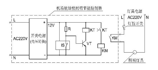
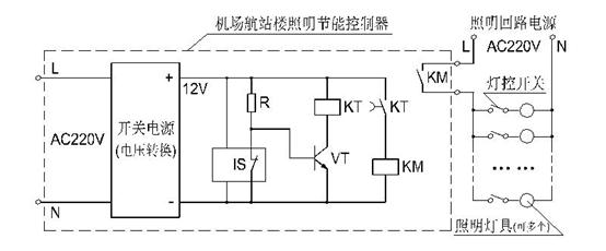
[0022] Refer below Figure 1 ~ Figure 2 The present invention will be described in detail.

[0023] Such as Figure 1 ~ Figure 2 As shown, the airport terminal lighting energy-saving controller of the present invention includes: a switching power supply, a control circuit board, an illuminance meter module IS, a resistor R, a triode VT, a time relay KT, and a small contactor KM. The illuminance meter module IS adopts a module that can pre-adjust the set illuminance value and has an output contact.

[0024] The main principle of the airport terminal lighting energy-saving controller of the present invention is to detect whether the indoor illuminance reaches the set interval value through the illuminance meter module IS, and if it reaches the upper limit of the set interval illuminance value, a switch signal is sent to disconnect the relevant lighting Power supply; if the lower limit of the illuminance value of the set interval is not reached, a switch signal is sent to turn ...


PUM


Abstract

The invention discloses a lighting and energy-saving control system for an airport terminal, which relates to the lighting and energy-saving control system. The control system comprises a switch power, a control circuit board, an illuminometer module IS, a resistor R, a triode VT, a time relay KT and a small-sized contactor KM, wherein the switch power, a delay circuit and a lighting power switch-on and switch-off circuit are arranged on the control circuit board; the illuminometer module IS is a module which can adjust and set an illumination value in advance and is provided with an output contact, can control a single lamp, and also can control a plurality of lamps or a plurality of loops at the same time. The distribution points of the illuminometer module indoors are coincident with the depth position of the controllable lamp indoors. The illuminometer module measures the illumination value in the airport terminal to judge whether a switch signal is sent or not and switches on or off the corresponding lighting power loop, so that electric energy are greatly reduced, the airport operating cost and pollution are reduced, and low-carbon and environmental-friendly effects are achieved.

Description

technical field [0001] The invention relates to an energy-saving lighting control system, in particular to an energy-saving lighting control system for a civil airport terminal building. Background technique [0002] With the rapid development of the country's economy, a large number of civil airports have been newly built, rebuilt, and expanded throughout the country in the past 30 years of reform and opening up, but there is still a big gap compared with developed countries such as Europe and the United States. According to authoritative statistics, in 2007, in Mainland China The ratio of the total number of civil airports to the total number of civil airports in the United States is only 2.9%, and the ratio of airports per capita is only 0.6%. Therefore, in the next few decades, China will still build, renovate and expand a large number of airport terminals to adapt to the continuous development of the civil aviation industry. According to the needs, by 2020, the total num...

Claims


Application Information

Patent Timeline
Patent Type & Authority Applications(China)
IPC IPC(8): H05B37/02
CPCY02B20/40Y02B20/42
Inventor 郭晓岩
Owner NORTHEASTERN UNIV
Why Eureka
Try Eureka