
Micro-saw blade for bone-cutting surgical saws

A surgical saw and cutting blade technology, applied in the field of micro saw blades

Active Publication Date: 2011-06-15
MEDTRONIC PS MEDICAL
View PDF7 Cites 11 Cited by
  • Summary
  • Abstract
  • Description
  • Claims
  • Application Information

AI Technical Summary

Problems solved by technology

This can result in a cutting width significantly greater than the width of the saw blade

Method used


Image

  • Micro-saw blade for bone-cutting surgical saws
  • Micro-saw blade for bone-cutting surgical saws
  • Micro-saw blade for bone-cutting surgical saws

Examples


Embodiment Construction

[0021] For the purpose of promoting an understanding of the principles of the invention, reference will be made to the embodiment or implementations illustrated in the drawings and specific language will be used to describe them. It should be understood however that no limitation of the scope of the invention is thereby intended. Any alterations and further modifications in the described embodiments, and any further applications of the principles of the invention described herein are contemplated as would normally occur to one skilled in the art to which this disclosure pertains.

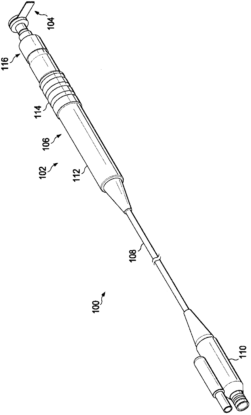
[0022] In general, the present disclosure relates to bone cutting surgical systems including handheld, high speed bone cutting surgical saws, such as sagittal or oscillating saws, and cutting microsaw blades. The saw includes a collet assembly having a protruding pin or nub that engages or protrudes into an opening in the cutting blade, thereby securing the blade in place in the collet assembly . ...


PUM


Abstract

The invention provides a surgical cutting blade for cutting bone material when the blade is coupled to a hand-held surgical saw having protrusions extending therefrom that interface with the cutting blade. The cutting blade includes a distal end comprising a plurality of cutting teeth and a shank portion adjacent the distal end. It also includes a proximal end adjacent the shank portion. The proximal end is shaped to attach to the surgical saw and includes an upper substantially planar surface and a lower substantially planar surface and a side edge extending between the upper and lower planar surfaces. The side edge at least in part defines an outer perimeter extending about the proximal end. The outer perimeter includes a plurality of indentations forming openings configured to receive and interface with the protrusions of the surgical saw in a manner that the protrusions cooperatively impart motion to drive the blade.

Description

technical field [0001] The present invention relates to bone cutting surgical systems, and more particularly to microsaw blades suitable for use with surgical cutting saws. Background technique [0002] Bone cutting surgical saws such as sagittal or oscillating type surgical saws cut most effectively at very high speeds, such as, for example, 10000-4000 revolutions per minute. This high speed causes a lot of vibration and can deflect the blade during cutting. The blade cuts therefore typically have a thickness significantly greater than the actual blade width. For example, a blade with a thickness of 0.015 inches may not be able to cut a trench with a width of less than 0.030 inches. Furthermore, since the saw operates at such high speeds, the excessive vibration tires the physician's hands and wrists quickly. When fatigue sets in, maintaining the same accuracy and precision can become more difficult. [0003] It is the way the blade is attached to the saw that is causin...

Claims


Application Information

Patent Timeline
IPC IPC(8): A61B17/14B27B33/02B23D61/12B27B19/00
CPCB27B19/006B23D61/006B27B33/02B27B5/32B23D61/125A61B17/148A61C3/12A61B17/14A61B17/141A61B17/142A61B17/1613
Inventor C·M·博伊金
Owner MEDTRONIC PS MEDICAL
Learn More