Supercharge Your Innovation With Domain-Expert AI Agents!

Method in a wireless communication system

A wireless communication system and reference signal technology, applied in the field of central nodes and remote remote nodes, to achieve enhanced capacity and improved channel evaluation performance

Active Publication Date: 2012-06-20
HUAWEI TECH CO LTD
View PDF0 Cites 1 Cited by
  • Summary
  • Abstract
  • Description
  • Claims
  • Application Information

AI Technical Summary

Problems solved by technology

Therefore, there is no set of reference signals that need to be shared among users in the system

Method used


Image

  • Method in a wireless communication system
  • Method in a wireless communication system
  • Method in a wireless communication system

Examples


Embodiment Construction

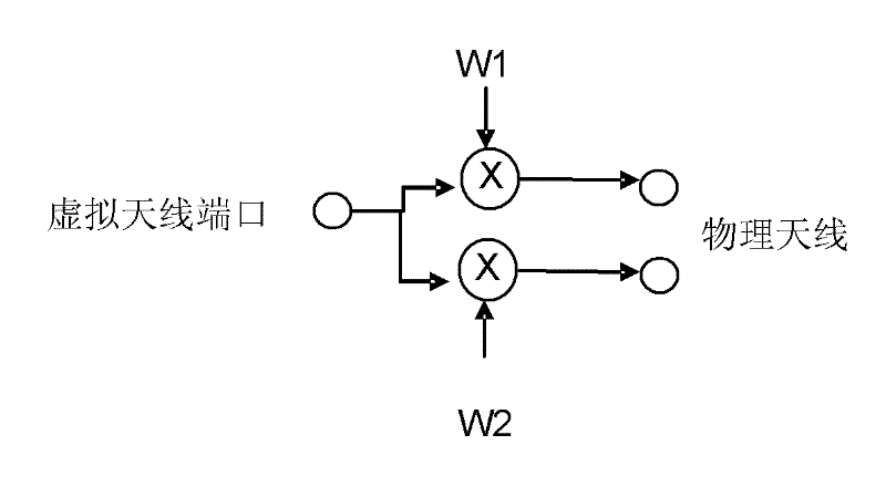
[0028] The user terminal may have multiple physical antennas. If the same signal is transmitted from multiple physical antennas at the same time, these physical antennas can be jointly regarded as a logically / electronically large virtual antenna composed of multiple physical antennas. From the receiver's perspective, physical antennas are transparent, which means that they cannot be distinguished independently. If each physical antenna is multiplied by a complex-valued constant, the concept of virtual antennas is still valid. In this case, the virtual antenna is obtained by linear mapping from the virtual antenna port (or equivalent virtual antenna input) to the physical antenna. Regardless of the content transmitted from the virtual antenna, a defined mapping will occur and the transmission from the physical antenna will occur. image 3 An example of mapping a virtual antenna port to two physical antennas is shown.

[0029] The mapping is usually described by the connection fr...


PUM


Abstract

A method in a Central Node (CN), a method in a Remote Node (CN), and a method in a wireless communication system for allocating reference signals are to be used for uplink transmission. According to one aspect of the invention reference signals are allocated with a method comprising the steps of: determining in a CN a number of reference signals N to be used for uplink transmission by a Remote Node RN; indicating to the RN the number of reference signals N to be used for uplink transmission by the RN; configuring an uplink transmission by the RN with at most the number of reference signals N; and performing by the RN the uplink transmission with at most the number of reference signals N on transmit antennas comprised in the RN. The reference signals are demodulation reference signals which have a subset being limited. A CN and a RN relating to the methods are provided.

Description

Technical field [0001] The present invention is related to a method in a central node that allocates reference signals for uplink transmission in a wireless communication system, a method in a remote range node, and a method in a wireless communication system, and also discloses a central node related to the above method. Node and remote remote node. Background technique [0002] A mobile station (MS) may have multiple physical antennas, and each physical antenna has a corresponding transmit power amplifier. A sounding reference signal (SRS) is transmitted from each physical antenna for measurement at the receiving base station (BS). The SRS from different antennas can be multiplexed by code, frequency or time. In addition, the SRS of all users in the cell needs to be multiplexed. SRS resources are allocated to different MSs in a semi-static mode by high-level signaling from the BS to the MS. [0003] In addition, in order to coherently demodulate the transmitted signal at the r...

Claims


Application Information

Patent Timeline
Patent Type & Authority Patents(China)
IPC IPC(8): H04B7/26
CPCH04L5/0091H04L25/0226H04L1/06H04L1/1607H04L1/1861H04L5/0051H04L5/0048H04W72/04
Inventor 马蒂尔斯·温斯特姆刘江华布兰尼斯拉夫·波波维奇
Owner HUAWEI TECH CO LTD
Features
  • R&D
  • Intellectual Property
  • Life Sciences
  • Materials
  • Tech Scout
  • Unparalleled Data Quality
  • Higher Quality Content
  • 60% Fewer Hallucinations
Learn More