Supercharge Your Innovation With Domain-Expert AI Agents!

Circuit arrangement and method for operating at least one lighting device

A technology for circuit devices and lighting devices, applied in the field of circuit devices, capable of solving problems such as low surge intensity

Inactive Publication Date: 2014-03-19
OSRAM GMBH
View PDF4 Cites 0 Cited by
  • Summary
  • Abstract
  • Description
  • Claims
  • Application Information

AI Technical Summary

Problems solved by technology

[0012] However, a problem arises when a surge pulse occurs between the inputs K1-1 and K1-2: As experience has shown, the circuit arrangement shown in FIG. 1 and known from the prior art has an undesired low surge strength

Method used


Image

  • Circuit arrangement and method for operating at least one lighting device
  • Circuit arrangement and method for operating at least one lighting device

Examples


Embodiment Construction

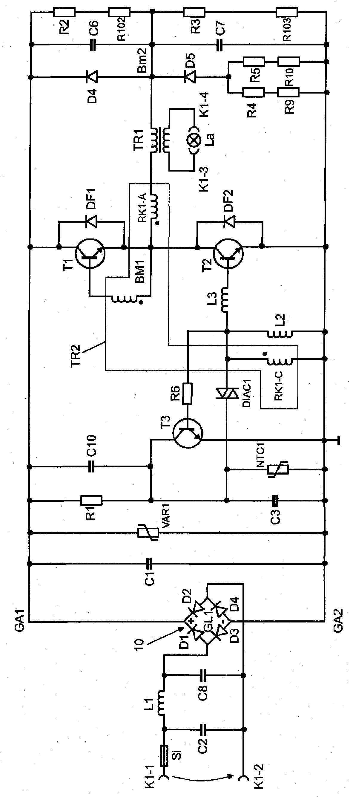
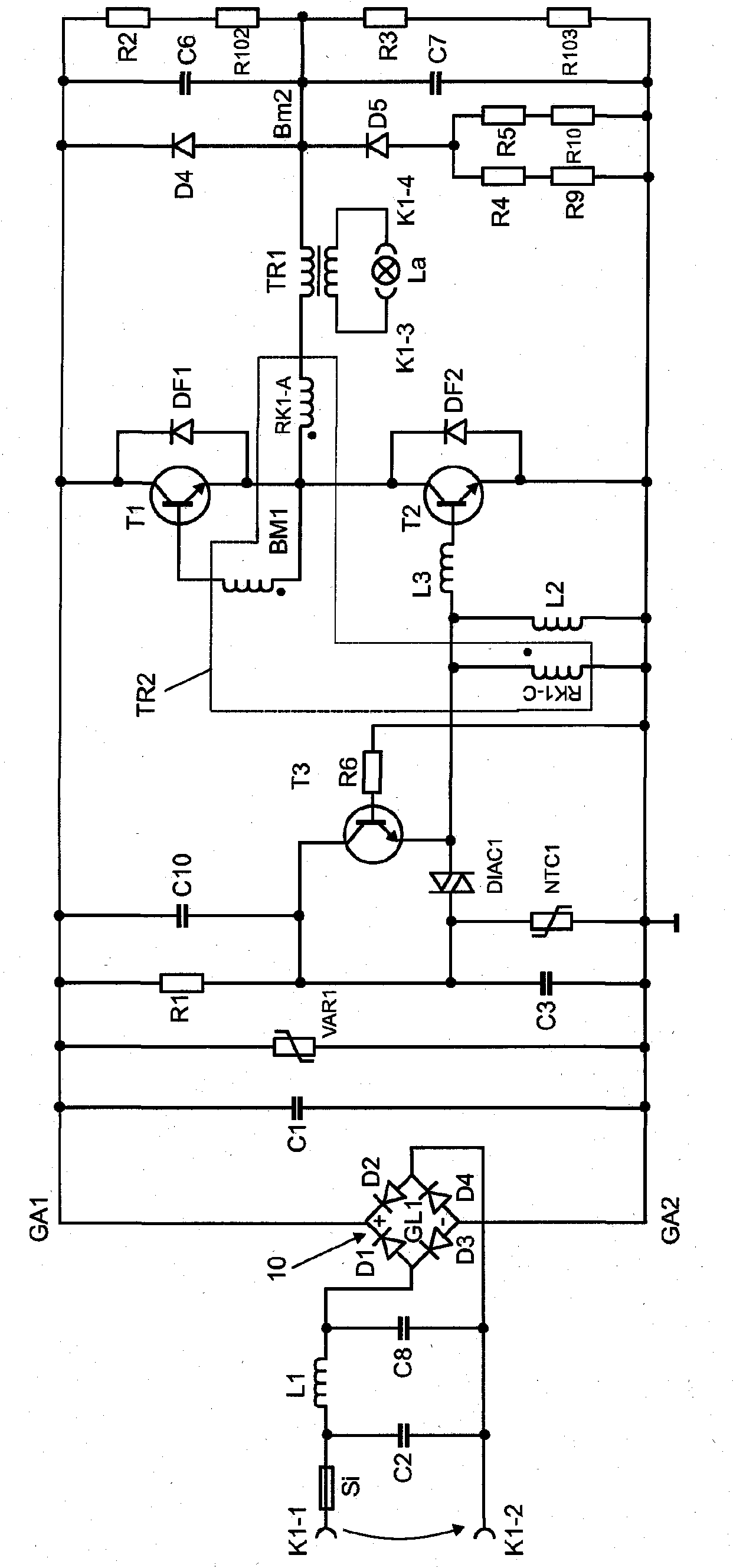
[0031] Reference numerals introduced with reference to FIG. 1 continue to be used for figure 2 Identical and corresponding components of the embodiment of the circuit arrangement according to the invention shown in , and will not be described again. Rather, only the differences from the known circuit arrangement shown in FIG. 1 are discussed.

[0032] exist figure 2 In the embodiment shown in , the control electrode of transistor T3 is coupled to the reference potential, while the reference electrode of transistor T3 is coupled to the third winding RK1-C of transformer TR2. In contrast, the control electrode of transistor T2 is also coupled to the third winding RK1 -C of transformer TR2 , while the reference electrode of transistor T2 is also coupled to a reference potential. This results in the actuation of transistor T3 with a phase shift of 180° relative to FIG. 1 , with reference to the actuation of transistor T2 . Thus, at the moment in which transistor T1 is on, ie tr...


PUM


Abstract

The present invention relates to a circuit arrangement for operating at least one lighting device (La), comprising an input, which has a first (K1-1) and a second input connection (K1-2) for connecting a supply voltage (UN), an output, which has a first (K1-3) and a second output connection (K1-4) for connecting the at least one lighting device, a rectifier (10), which at the input side is coupled to the first (K1-1) and the second input connection (K1-2), wherein the rectifier (10) has an output with a first (GA1) and a second output connection (GA2), a bridge circuit having a first (BM1) and a second bridge center (BM2), wherein the bridge circuit comprises at least one first (T1) and a second electronic switch (T2), wherein each electronic switch (T1; T2) has a control electrode, a reference electrode, and a working electrode, wherein the reference electrode of the first electronic switch (T1) is coupled to the working electrode of the second electronic switch (T2) to form the first bridge center (BM1), a first transformer (TR1) having a first and a second winding, wherein the first winding is coupled between the first (BM1) and the second bridge center (BM2), wherein a first connection of the second winding is coupled to the first output connection (K1-3) and a second connection of the second winding is coupled to the second output connection (K1-4) of the circuit arrangement, a second transformer (TR2) having a first (RK1-A), a second (RK1-B), and a third winding (RK1-C), wherein the first winding (RK1-A) is coupled in series to the first winding of the first transformer (TR1), wherein the second winding (RK1-B) is coupled between the control electrode and the reference electrode of the first electronic switch (T1) and the third winding (RK1-C) is coupled between the control electrode and the reference electrode of the second electronic switch (T2), a first capacitor (C3), the first connection of which is coupled to the first output connection (GA1) of the rectifier (10) and the second connection of which is coupled to the second output connection (GA2) of the rectifier (10), an ignition unit (DIAC1), the first connection of which is coupled to the first connection of the first capacitor (C3) and the second connection of which is coupled to the control electrode of the second electronic switch (T3), and a third electronic switch (T3), which has a control electrode, a reference electrode, and a working electrode, wherein the working electrode of the third electronic switch (T3) is coupled to the first output connection (GA1) of the rectifier (10), wherein the reference electrode of the third electronic switch (T3) is coupled to the control electrode of the second electronic switch (T2), and the control electrode of the third electronic switch (T3) is coupled to the reference electrode of the second electronic switch (T2). The invention further relates to a corresponding method for operating at least one lighting device (La).

Description

technical field [0001] The invention relates to a circuit arrangement for operating at least one lighting device, which has an input with a first input connection and a second input connection for connecting a supply voltage, an output with a first output terminal and a second output terminal for connecting the at least one lighting device; a rectifier coupled to the first input terminal and the second input terminal on the input side, wherein the rectifier has a first output terminal and a second output terminal Output; a bridge circuit with a first bridge midpoint and a second bridge midpoint, wherein the bridge circuit comprises at least one first electronic switch and at least one second electronic switch, wherein each electronic switch has a control electrode, a reference electrode and working electrode, wherein the reference electrode of the first electronic switch is coupled to the working electrode of the second electronic switch to construct a first bridge midpoint; a...

Claims


Application Information

Patent Timeline
Patent Type & Authority Patents(China)
IPC IPC(8): H05B39/04
CPCH05B39/045Y02B20/142Y02B20/00H05B39/04H05B39/00
Inventor 安德烈亚斯·胡贝尔赫尔穆特·霍伊瑟
Owner OSRAM GMBH
Features
  • R&D
  • Intellectual Property
  • Life Sciences
  • Materials
  • Tech Scout
  • Unparalleled Data Quality
  • Higher Quality Content
  • 60% Fewer Hallucinations
Learn More