Electric lock cylinder

A technology of electric locks and lock cylinders, applied in the field of locks, to achieve the effect of simple operation and automatic integration

Active Publication Date: 2012-10-03
梁忠祥
View PDF0 Cites 4 Cited by
  • Summary
  • Abstract
  • Description
  • Claims
  • Application Information

AI Technical Summary

Problems solved by technology

[0003] The purpose of the present invention is to provide an electric lock cylinder to solve technical problems such as convenient unlocking and common use of lock cylinders.

Method used


Image

  • Electric lock cylinder
  • Electric lock cylinder
  • Electric lock cylinder

Examples


Embodiment Construction

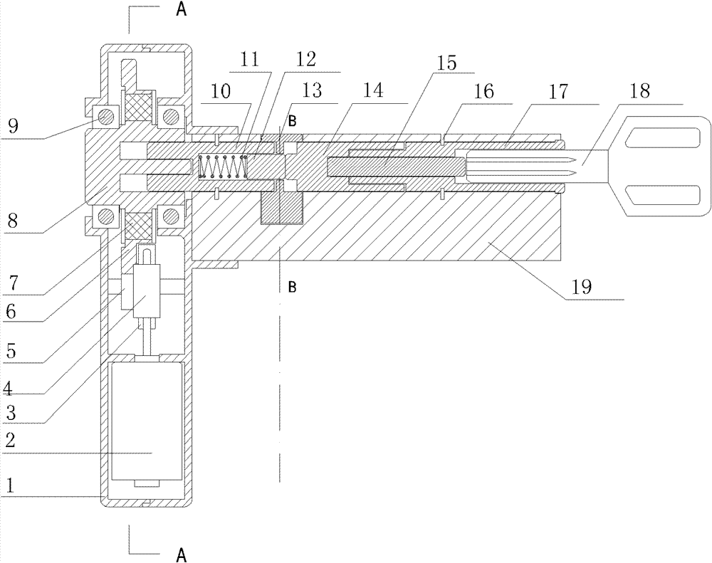
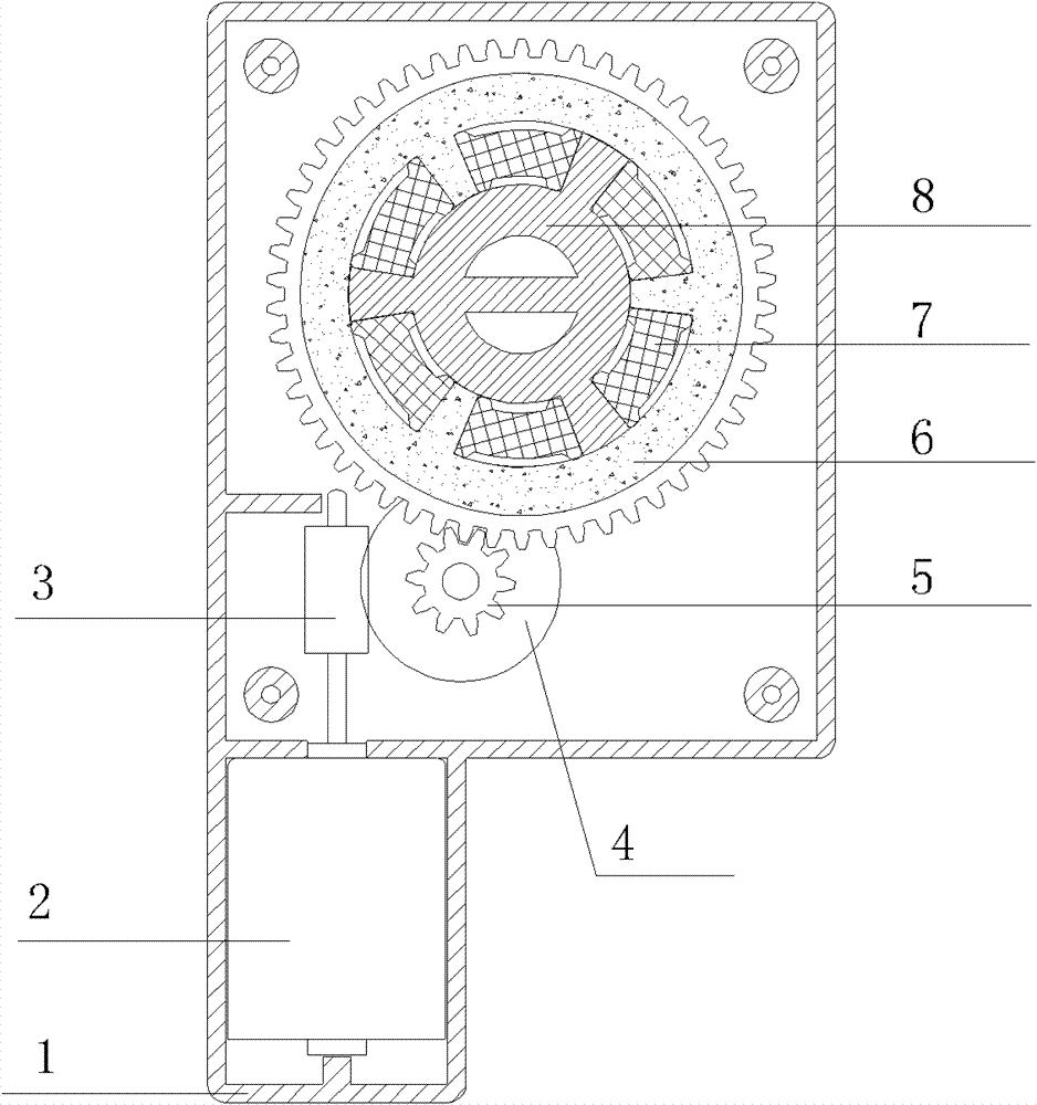
[0020] The present invention mainly is made up of gearbox, mechanical lock cylinder two parts. Structure and working principle of the present invention refer to figure 1 , wherein the gearbox comprises a motor 2, a worm 3 connected to the output shaft of the motor, a worm gear 4 engaged with the worm, a first gear 5 coaxially fixed with the worm gear, and a second gear 6 engaged with the first gear. The second gear is connected with the output shaft 8, and a rubber pad 7 is installed on the connection surface between the second gear and the output shaft 8 to buffer the transmission, and the two ends of the output shaft are equipped with bearings 9 fixed on the housing 1. The cross-sectional diagram of the specific gearbox structure is shown in image 3 shown.

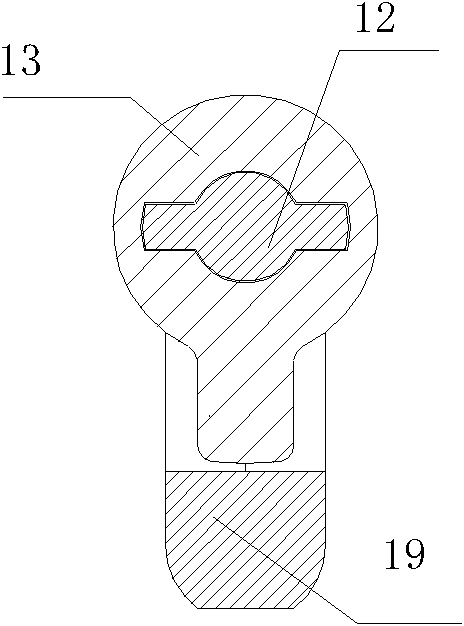
[0021] One end of the mechanical lock cylinder housing 19 is equipped with a linkage shaft 10, and one end of the linkage shaft is provided with a longitudinal notch, and a first linkage pin 12 is housed in the notch,...


PUM


Abstract

The invention discloses an electric lock cylinder. The electric lock cylinder comprises a gearbox and a mechanical lock cylinder. The gearbox comprises a shell, a motor, a worm, a worm wheel, a first gear, a second gear and an output shaft. A linkage shaft is arranged at one end of a mechanical lock cylinder shell, a first linkage pin is arranged in one end of the linkage shaft, the first linkagepin is linked with a dial wheel in an inserted mode, a spring is arranged between the linkage shaft and the first linkage pin, and the other end of the linkage shaft is connected with the output shaft of the gearbox; and a lock cylinder rotating shaft is arranged at the other end of the mechanical lock cylinder shell, one end of the lock cylinder rotating shaft is spliced with one end of a secondlinkage pin, the longitudinal center of the lock cylinder rotating shaft is provided with a circular hole, an ejector rod is placed in the circular hole, a dead bolt key is assembled at the other endof the lock cylinder rotating shaft, the other end of the second linkage pin is spliced with the dial wheel, the end face of a raised key of the second linkage pin is contacted with the end face of the first linkage pin, the other end of the second linkage pin is provided with a blind hole, and the size of the blind hole is adapted with one end of the ejector rod in a splicing way. The electric lock cylinder can solve the technical problems of convenience for unlocking, universality of the lock cylinder and the like.

Description

technical field [0001] The invention relates to a lock set combining electronics and mechanics. Background technique [0002] Existing anti-theft doors generally adopt pin-plug mechanical locks. During operation, the key needs to be accurately inserted into the lock core and rotated a few times before the lock can be unlocked. After unlocking, the key can only be pulled out by rotating in the opposite direction and finding the correct position. The operation is cumbersome. Especially under the condition of dim light, it is difficult to find the keyhole, which brings inconvenience to the elderly and children. Contents of the invention [0003] The object of the present invention is to provide an electric lock cylinder to solve technical problems such as convenient unlocking and common use of lock cylinders. [0004] The present invention realizes the object of the above invention through the following technical solutions: an electric lock cylinder, which is composed of a g...

Claims


Application Information

Patent Timeline
Patent Type & Authority Patents(China)
IPC IPC(8): E05B47/00E05B15/00
Inventor 梁忠祥
Owner 梁忠祥
Why Eureka
Try Eureka