Screen unit

A technology for projection screens and supporting parts, which is applied to projection devices, optics, instruments, etc., and can solve problems such as uneven tension of projection screens and decreased flatness of projection screens

Active Publication Date: 2011-06-22
SEIKO EPSON CORP
View PDF3 Cites 22 Cited by
  • Summary
  • Abstract
  • Description
  • Claims
  • Application Information

AI Technical Summary

Problems solved by technology

Once the above situation occurs, the tension applied to the projection screen will be uneven and the flatness of the projection screen will decrease.

Method used


Image

  • Screen unit
  • Screen unit
  • Screen unit

Examples


no. 1 Embodiment approach

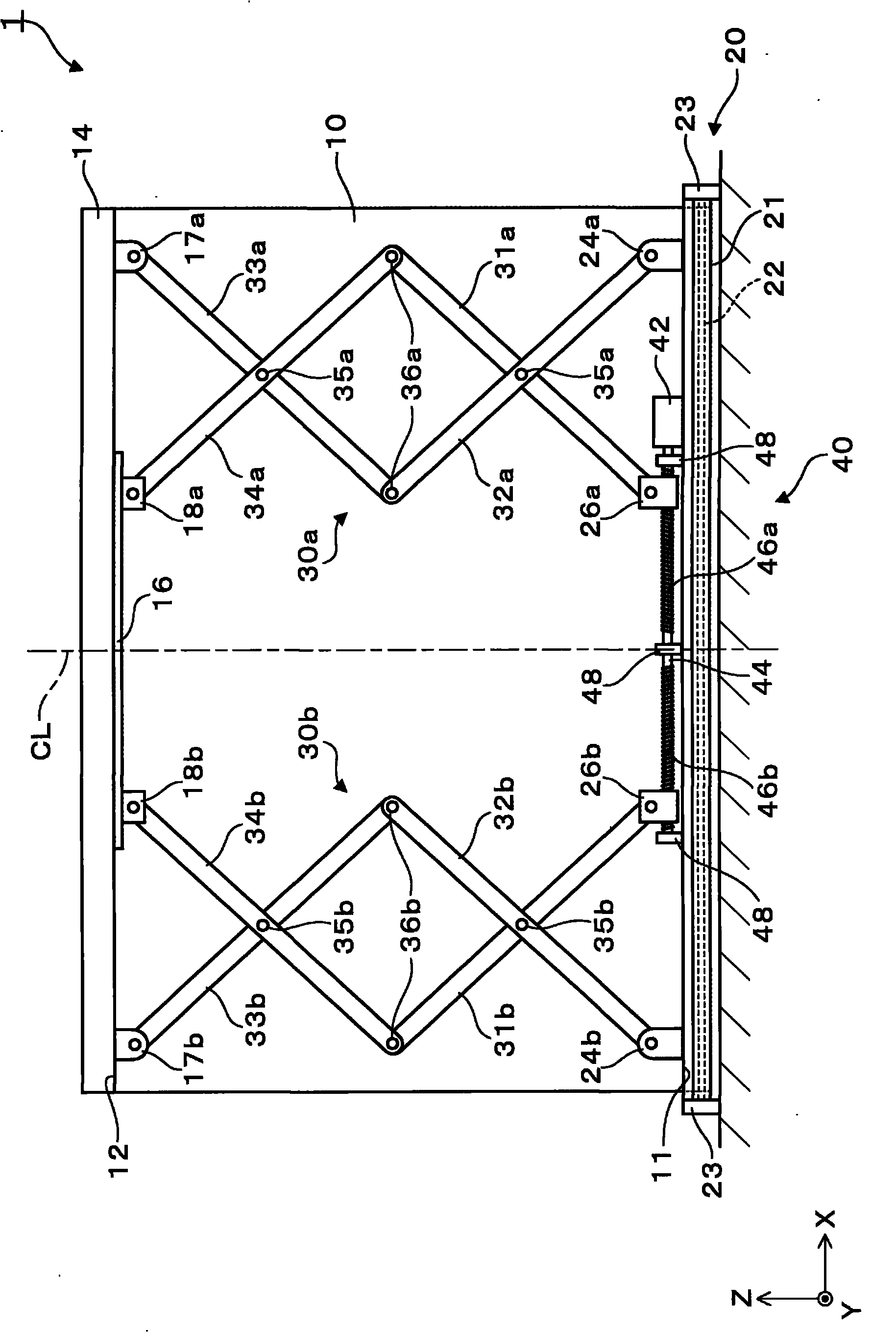
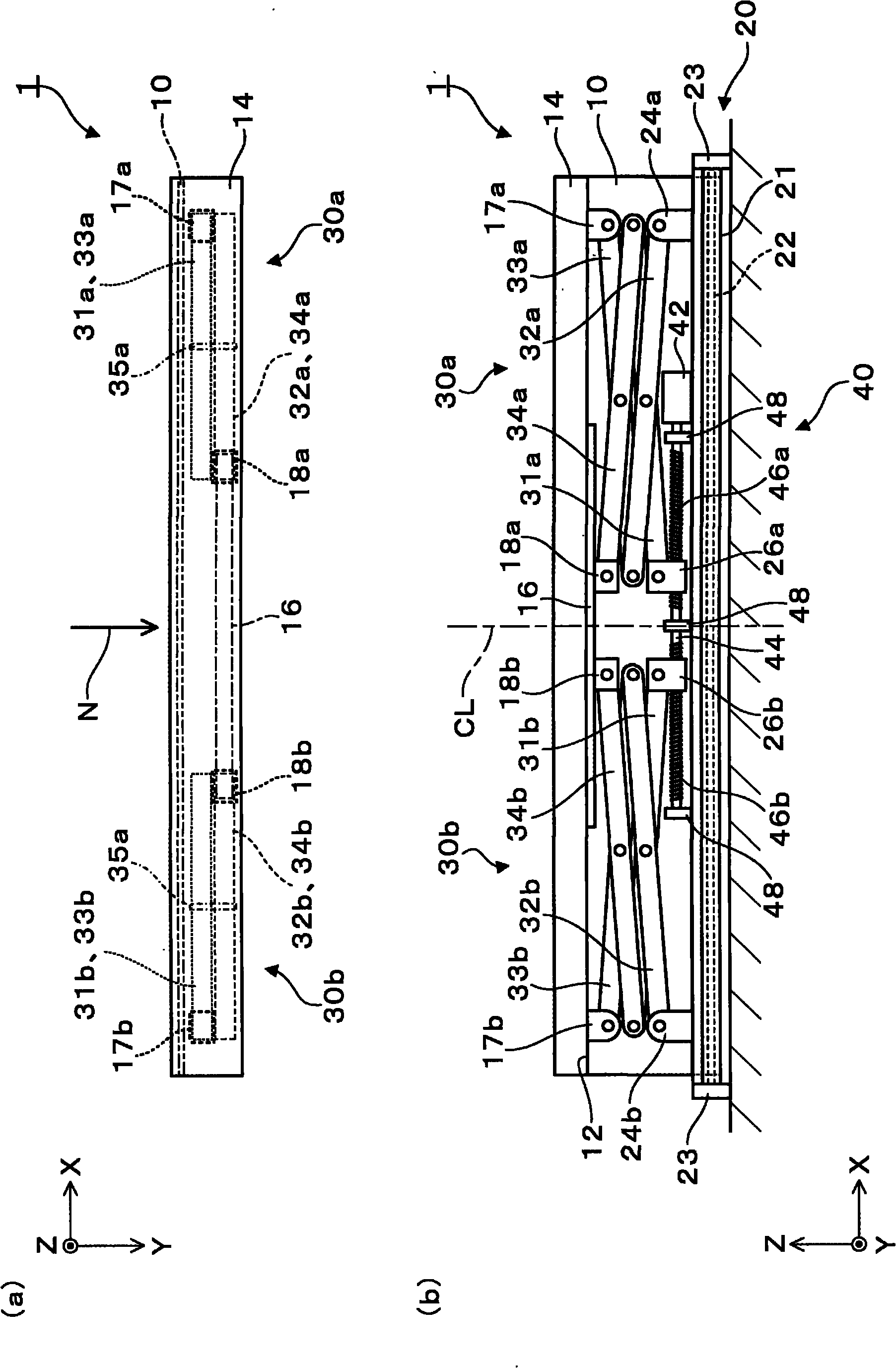
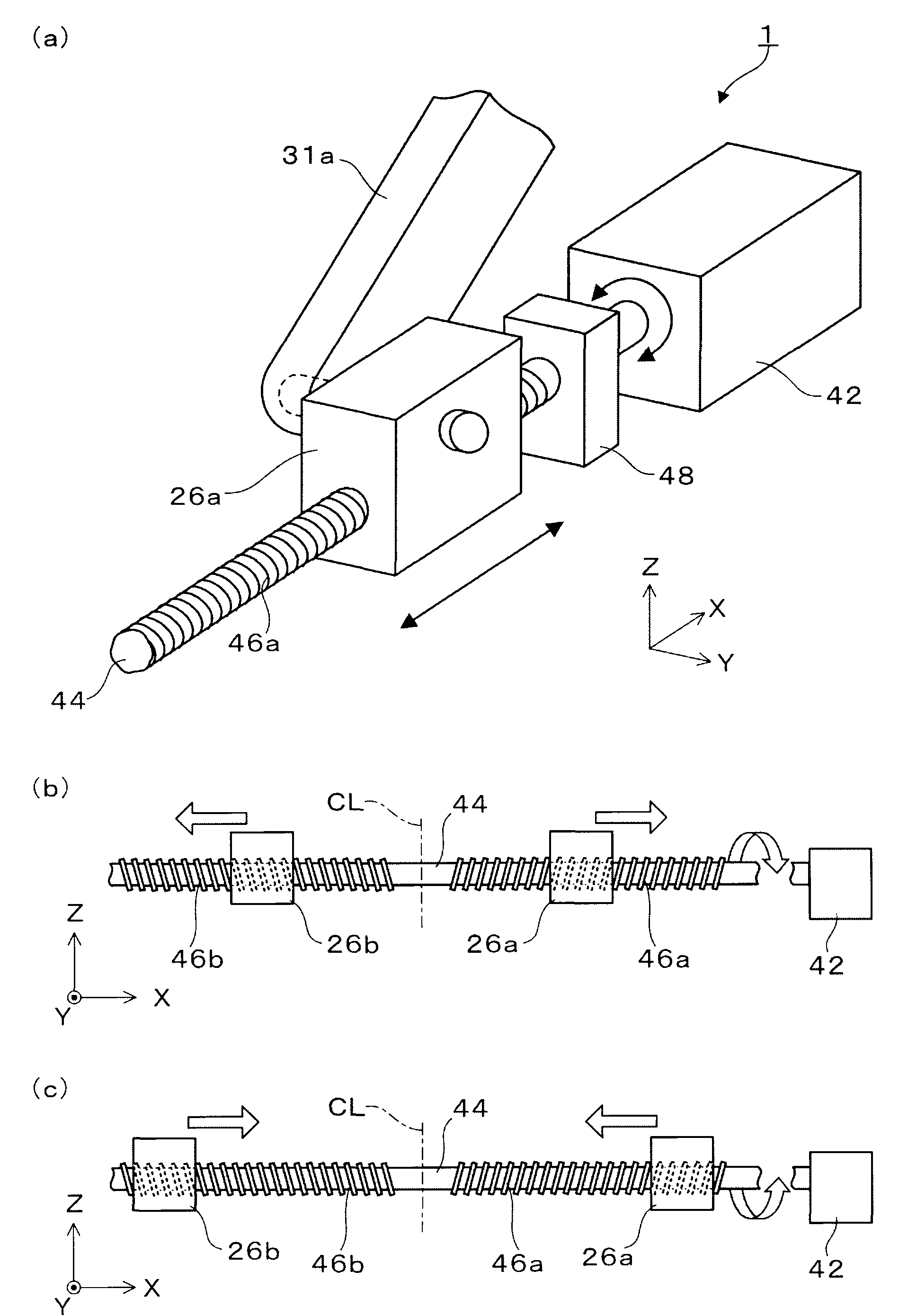
[0039] First, refer to figure 1 , figure 2 ,and image 3 The projection screen device according to the first embodiment will be described. figure 1 and figure 2 It is a figure explaining the schematic structure of the projection screen apparatus concerning 1st Embodiment. in particular, figure 1 It is a schematic view viewed from the rear side of the projection screen device in an unfolded state. figure 2 (a) is a schematic view viewed from above the projection screen device in an unfolded state, figure 2 (b) is a schematic diagram viewed from the rear side of the projection screen device in a housed state. image 3 It is a figure explaining the rotation mechanism concerning 1st Embodiment. in particular, image 3 (a) is a perspective view showing the structure of the main part of the rotation mechanism, image 3 (b) and (c) are figures explaining the operation|movement of a rotation mechanism.

[0040] Such as figure 1 As shown, the projection screen device 1 a...

no. 2 Embodiment approach

[0089] Next, a diagram of a projection screen device according to the second embodiment will be described with reference to the drawings. Figure 4 It is a figure explaining the schematic structure of the projection screen apparatus concerning 2nd Embodiment. In detail, Figure 4 It is a schematic diagram of the main part of the projection screen device viewed from the rear side.

[0090] The projection screen device according to the second embodiment differs from the projection screen device according to the first embodiment in the configuration of the rotation mechanism, and the other configurations are the same. Components common to those of the first embodiment are assigned the same reference numerals, and description thereof will be omitted.

[0091] refer to Figure 4 , the configuration of the projection screen device 2 according to the second embodiment will be described. The projection screen device 2 according to the second embodiment is a projection screen devic...

no. 3 Embodiment approach

[0104] Next, a projection screen device according to a third embodiment will be described with reference to the drawings. Figure 5 It is a figure explaining the schematic structure of the projection screen apparatus concerning 3rd Embodiment. in particular, Figure 5 It is a schematic diagram of the main part of the projection screen device viewed from the rear side.

[0105] The projection screen device according to the third embodiment is different from the projection screen device according to the second embodiment in that it includes a rotation mechanism corresponding to the installation on the ceiling surface, and other configurations are substantially the same. Components common to those of the second embodiment are given the same reference numerals, and description thereof will be omitted.

[0106] refer to Figure 5 , the configuration of the projection screen device 3 according to the third embodiment will be described. The projection screen device 3 according to...


PUM


Abstract

The invention provides a screen unit capable of inhibiting the screen from deflecting, offsetting or twisting even the screen is expanded.A screen unit includes: a screen which has a first side and a second side opposing to each other in a first direction and extending substantially in parallel with each other; a first supporting portion extending along the first side to support the first side; a second supporting portion extending along the second side to support the second side; and a plurality of connecting mechanisms each of which extends between the first supporting portion and the second supporting portion, and expands and contracts in the first direction to move the second supporting portion close to and away from the first supporting portion, wherein the plurality of connecting mechanisms are disposed in parallel with the first supporting portion, and are located almost linearly symmetric with respect to a center line connecting approximately the center of the first side and approximately the center of the second side.

Description

technical field [0001] The present invention relates to projection screen devices. Background technique [0002] There is known a projection screen device that projects an image emitted from a projection display device such as a projector, and that is deployed when in use and stored when not in use. In this projection screen device, a pantograph connection mechanism that connects a plurality of arms to each other is often used as a mechanism for lifting and lowering the projection screen when unfolding and storing the projection screen, and for supporting the projection screen when the projection screen is unfolded. organization. [0003] As a configuration of the connection mechanism, for example, a configuration in which arms are connected in a rhombus shape and supported at one point near the center of the upper end of the projection screen is known. In addition, there is also disclosed a configuration in which arms are cross-connected in a substantially X-shape to supp...

Claims


Application Information

Patent Timeline
Patent Type & Authority Applications(China)
IPC IPC(8): G03B21/58G03B21/56
CPCG03B21/58
Inventor 黑井圣史桥爪秀敏
Owner SEIKO EPSON CORP
Why Eureka
Try Eureka