Motorized spindle structure for turning and milling
An electric spindle and dual-purpose technology, applied in the direction of metal processing equipment, etc., can solve problems such as fluttering and chipping, lower part surface processing quality, and complex structure of the whole machine, and achieve easy operation, small footprint, and increased use of space Effect
Inactive Publication Date: 2011-06-29
大连高金数控集团有限公司
View PDF6 Cites 5 Cited by
- Summary
- Abstract
- Description
- Claims
- Application Information
AI Technical Summary
Problems solved by technology
For example, when cutting a slender shaft, if the lower tool holder is used for turning, the lower tool holder and the center frame are likely to interfere, which will reduce the surface processing quality of the part and even cause chattering and chipping.
In addition, when the tool holder is arranged under the main shaft, chips and coolant will bring many difficulties to the protection of the lower guide rail pair, making the structure of the whole machine complex
Method used
View moreImage
Smart ImageViewing Examples
Examples
Embodiment Construction
Login to View More PUM
 Abstract
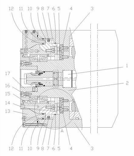
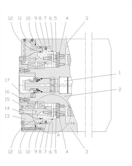
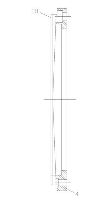
The invention discloses a motorized spindle structure for turning and milling, which comprises a box body and a spindle, wherein the spindle is arranged in the box body, the front end of the box body is fixedly connected with an end cover and a front bearing seat, a front bearing is arranged between the front part of the spindle and the front bearing seat, an annular space is left between the front bearing seat and the outside of the front part of the spindle, the inside of the annular space is provided with a piston body sleeved on the spindle, a front cavity is formed in the front of the piston body, a rear cavity is formed in the back of the piston body, the rear side face of the piston body is fixedly provided with an annular connecting-end fluted disc, a step at the front part of the spindle is fixedly provided with an annular inner-end fluted disc, a step at the front side of the box body is fixedly provided with an annular outer-end fluted disc, the teeth on the connecting-end fluted disc can be meshed with the teeth of the inner-end fluted disc, and the box body is provided with oil channels respectively connected with the front cavity and the rear cavity. The motorized spindle structure for turning and milling disclosed by the invention can carry out turning and milling conversion, and is very convenient, easy to operate and low in occupied space, so that the used space in a machine tool is increased.
Description
Dual-purpose electric spindle structure for turning and milling technical field The invention relates to an electric spindle structure, in particular to a dual-purpose electric spindle structure for turning and milling, which is mainly used in mechanical cutting machine tools. Background technique At present, the structure of the electric spindle in the machine tool has a box body, a main shaft is arranged in the box body, a broach mechanism is arranged at the inner hole of the main shaft, and the box body and the main shaft are supported by front and rear end covers and front and rear bearing seats. . A rotor winding is arranged on the main shaft, and a stator winding is arranged on the inner side of the box outside the rotor winding. When working, the rotor drives the main shaft to rotate relative to the box, and the milling cutter fixed by the broach mechanism can rotate with the main shaft to achieve the purpose of milling the workpiece. According to the regulations...
Claims
Login to View More Application Information
Patent Timeline
 Patent Type & Authority Applications(China)
IPC IPC(8): B23B19/00
Inventor 邹运刘明飞张允良
Owner 大连高金数控集团有限公司
- R&D Engineer
- R&D Manager
- IP Professional
- Industry Leading Data Capabilities
- Powerful AI technology
- Patent DNA Extraction
Learn More Browse by: Latest US Patents, China's latest patents, Technical Efficacy Thesaurus, Application Domain, Technology Topic, Popular Technical Reports.
© 2024 PatSnap. All rights reserved.Legal|Privacy policy|Modern Slavery Act Transparency Statement|Sitemap|About US| Contact US: help@patsnap.com


