
Vehicle body draft, bolster and buffer assembling and welding process

A technology for bolstering and assembling welding, which is applied to the machining of raw materials for bolstering of car body, aluminum alloy assembling welding product process, and assembling welding technology field, which can solve the problems of waste, inconvenient operation, easy generation of pores, etc., and reduce production. Cost and energy waste, guarantee of changes in material volume and size, and the effect of preventing deformation

Active Publication Date: 2012-12-12
南京雷尔伟新技术股份有限公司
View PDF0 Cites 0 Cited by
  • Summary
  • Abstract
  • Description
  • Claims
  • Application Information

AI Technical Summary

Problems solved by technology

But at present, in the process of aluminum alloy assembly and welding products in our country, especially the process of all-welded aluminum alloy assembly and welding in the assembly and welding process of car body, the process of all-welded aluminum alloy is still not perfect, and there are obviously complicated processes, too many links, and inconvenient operation. The problem is that it increases the production cost and energy waste, and aluminum alloy welding is easy to produce air holes and deformation. Therefore, for the welding parts of important parts of the vehicle, good assembly technology and welding technology must be used to ensure product quality.

Method used


Image

  • Vehicle body draft, bolster and buffer assembling and welding process
  • Vehicle body draft, bolster and buffer assembling and welding process
  • Vehicle body draft, bolster and buffer assembling and welding process

Examples


Embodiment Construction

[0030] In order to make the technical means, creative features, goals and effects achieved by the present invention easy to understand, the present invention will be further described below in conjunction with specific embodiments.

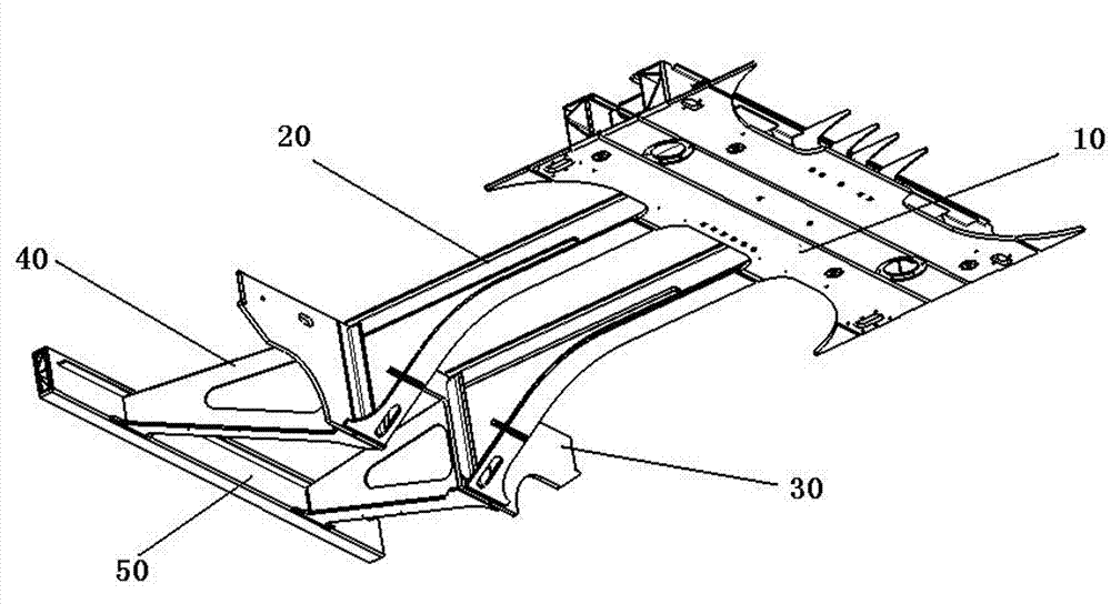
[0031] see figure 1 , the present invention provides an assembly welding process of the MP end car body lead pillow of aluminum weldment, the MP end lead pillow is composed of five parts: a bolster 10, a draw beam 20, a coupler mounting seat 30, a buffer beam 40, and an end beam 50 In the traction pillow 20 at the MP end, the upper plane of the corbel 10 is connected to the floor, and the lower plane is assembled with the bogie. The mounting hole on the coupler mounting seat 30 is assembled with the coupler, and the side is welded with the buffer beam 40, and the buffer beam 40 plays a role of buffering during the operation of the vehicle.

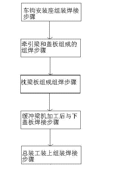
[0032] In this example, if figure 2 As shown, the above-mentioned corbel 10, traction beam 20, coupler m...


PUM


Abstract

The invention discloses a vehicle body draft, bolster and buffer assembling and welding process. The vehicle body draft, bolster and buffer comprises a body bolster, a draft sill, a coupler mounting base, a buffer sill and an end sill which are all made of aluminium alloy materials. The process comprises the following steps: (A) assembling and welding the coupler mounting base; (B) assembling andwelding the composition of the draft sill and a cover plate; (C) assembling and welding the components of a body bolster plate; (D) welding the buffer sill and a lower cover plate after machining thebuffer sill; and (E) assembling and welding the end sill, the buffer sill, the coupler mounting base, the draft sill and the body bolster on general assembly equipment; ensuring the verticality between the coupler mounting surface and the air spring mounting surface to be not more than 1.5mm; ensuring the deviation from the center of the coupler mounting base to the center of the air spring hole to be not more than + / -1mm; and ensuring the maximum straightness to be 2mm after assembling the end sill. The process has the beneficial effects of solving the problem of assembling and welding of the aluminium alloy structures of high-speed trains, collecting the parameters of aluminium alloy welding through experiments, perfecting the aluminium alloy assembling and welding process, preventing deformation after welding and variation of the material displacement size, ensuring the product quality and reducing the production cost and energy waste.

Description

technical field [0001] The invention relates to an aluminum alloy assembling and welding product process, in particular to a material machining and assembling process of a trinity of aluminum welded parts, which is a car body tension pillow, and belongs to the field of product manufacturing technology. Background technique [0002] Aluminum alloy has the advantages of light weight, corrosion resistance, good appearance flatness, easy manufacture of complex curved surfaces, high specific strength, etc., and has been valued by the track modification industry around the world. At present, my country's rail transit is facing the development of high-speed passenger cars, subway passenger cars, light rail trains and high-speed heavy-duty trucks. The lightweight of trains is the first choice for increasing the speed of trains. Aluminum alloy materials can reduce self-weight, reduce resistance during operation, reduce energy consumption, and increase load, so the railway transportat...

Claims


Application Information

Patent Timeline
Patent Type & Authority Patents(China)
IPC IPC(8): B23K31/02
Inventor 夏铁存刘俊张建彬顾铉
Owner 南京雷尔伟新技术股份有限公司
Learn More