Full-duplex wireless transceiver design

A transceiver, wireless technology, used in wireless communication, duplex signal operation, antenna and other directions, can solve the problems of difficult and expensive duplexer design

Inactive Publication Date: 2011-06-29
QUALCOMM INC
View PDF4 Cites 0 Cited by
  • Summary
  • Abstract
  • Description
  • Claims
  • Application Information

AI Technical Summary

Problems solved by technology

Additionally, the duplexer is required to introduce minimal insertion loss in the TX signal path as well as the RX signal path
These competing requirements make duplexer design for mobile phones difficult and expensive

Method used


Image

  • Full-duplex wireless transceiver design
  • Full-duplex wireless transceiver design
  • Full-duplex wireless transceiver design

Examples


Embodiment Construction

[0013] The present invention describes providing separate antennas for the TX signal path and the RX signal path in a mobile wireless device while minimizing cost and space.

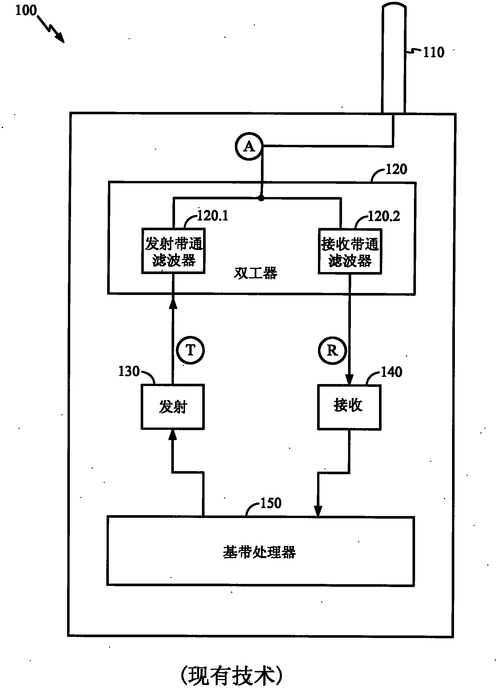
[0014] figure 1 A prior art implementation of a full-duplex wireless transceiver is depicted. Note that prior art implementations are shown for purposes of illustration only, and are not intended to limit the application of the techniques of this disclosure to any particular implementation of a wireless communication device. Those skilled in the art will recognize that a practical implementation of a wireless device will include figure 1 Components shown in .

[0015] exist figure 1 In the wireless transceiver 100 includes a baseband processor 150 coupled to a TX circuit 130 and an RX circuit 140 . TX circuit 130 and RX circuit 140 have node T and node R, respectively, both coupled to duplexer 120 . Duplexer 120 is also coupled to antenna 110 at node A. Note that duplexer 120 may include a TX bandp...


PUM


Abstract

Techniques are provided for full-duplex mobile wireless transceiver design without using duplexers. In an embodiment, separate antennas are provided for the TX and RX signal paths in the transceiver. In an embodiment, the antennas may be implemented as surface mountable ceramic antennas. In an embodiment, the antennas may incorporate integrated band-pass filtering. Further techniques for designing the antennas to have different relative physical characteristics, including antenna orientation, are disclosed.

Description

technical field [0001] The present invention relates to transceivers for wireless communication devices, and in particular, to mobile wireless transceivers featuring separate antennas for transmit and receive signal paths. Background technique [0002] A full-duplex transceiver is a device that supports simultaneous signal transmission (TX) and reception (RX). In mobile devices, wireless full-duplex transceivers typically feature separate TX and RX signal paths coupled to a single antenna via a duplexer. The duplexer allows both the TX circuit and the RX circuit to share the same antenna to save space and cost, while isolating the TX signal and the RX signal from each other. Since the TX signal and the RX signal usually occupy different frequency bands, the duplexer can incorporate a band-pass filtering function and a frequency multiplexing function. [0003] Stringent requirements are often imposed on duplexer designs, for example, for mobile telephones designed to operat...

Claims


Application Information

Patent Timeline
Patent Type & Authority Applications(China)
IPC IPC(8): H04B1/40H01Q1/52H01Q1/24
CPCH04B1/40H04B1/52H01Q1/525H04W88/02H04L5/14H01Q1/24H01Q1/52
Inventor 章扬
Owner QUALCOMM INC
Why Eureka
Try Eureka