
Device for detecting and adjusting gas outlet flow of lighter

A technology for regulating devices and air flow, which is applied in the direction of combustion ignition, lighting and heating equipment, and combustion methods. It can solve the problems of large impact on lighter structure, high detection environment requirements, and complex circuit structure, so as to avoid damage to plastic parts by flames. Impact, low requirements for the detection environment, and the effect of simplifying the detection equipment

Active Publication Date: 2011-07-06
XINHAI TECH GRP CO LTD
View PDF7 Cites 6 Cited by
  • Summary
  • Abstract
  • Description
  • Claims
  • Application Information

AI Technical Summary

Problems solved by technology

This device needs to sense the flame through the thermocouple, so it needs to design a complex circuit structure, and the thermocouple needs to be maintained frequently to prevent the sensitivity of the thermocouple from degrading
In addition, the above measuring devices all need to ignite the lighter and then measure the flame. Only the lighter with no plastic parts in the flame involved after the lighter is ignited can be tested, otherwise the flame will melt the plastic parts, which is greatly affected by the structure of the lighter itself. It is suitable for testing some models; it has high requirements for the testing environment (such as windproof); after measuring the flame height, the lighters that do not meet the requirements are screened out, and then the adjustment is still done manually, without synchronous adjustment after the test. Repeated testing is required, and the efficiency is low

Method used


Image

  • Device for detecting and adjusting gas outlet flow of lighter
  • Device for detecting and adjusting gas outlet flow of lighter
  • Device for detecting and adjusting gas outlet flow of lighter

Examples


Embodiment Construction

[0022] The present invention will be further described below with reference to the accompanying drawings.

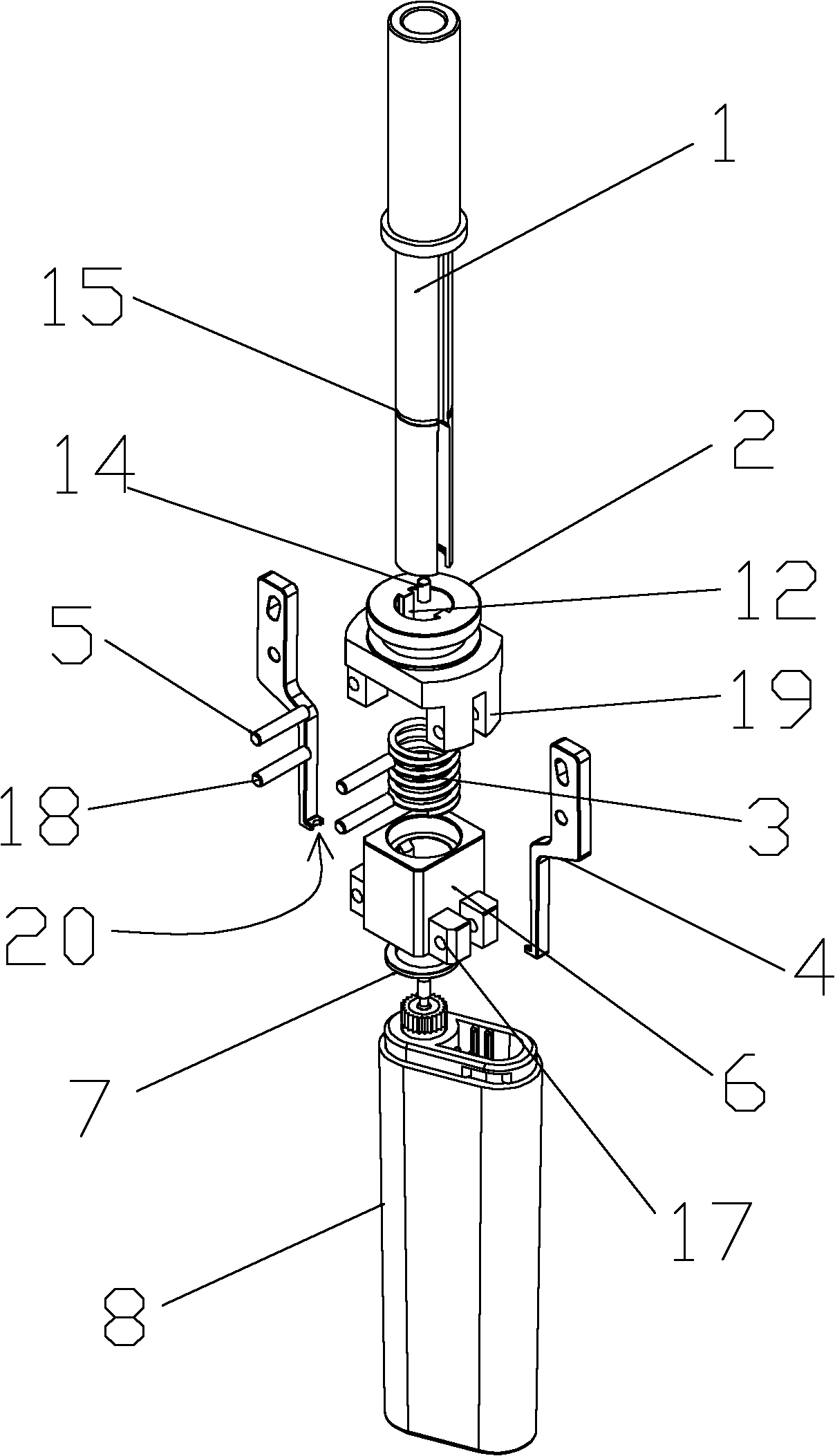
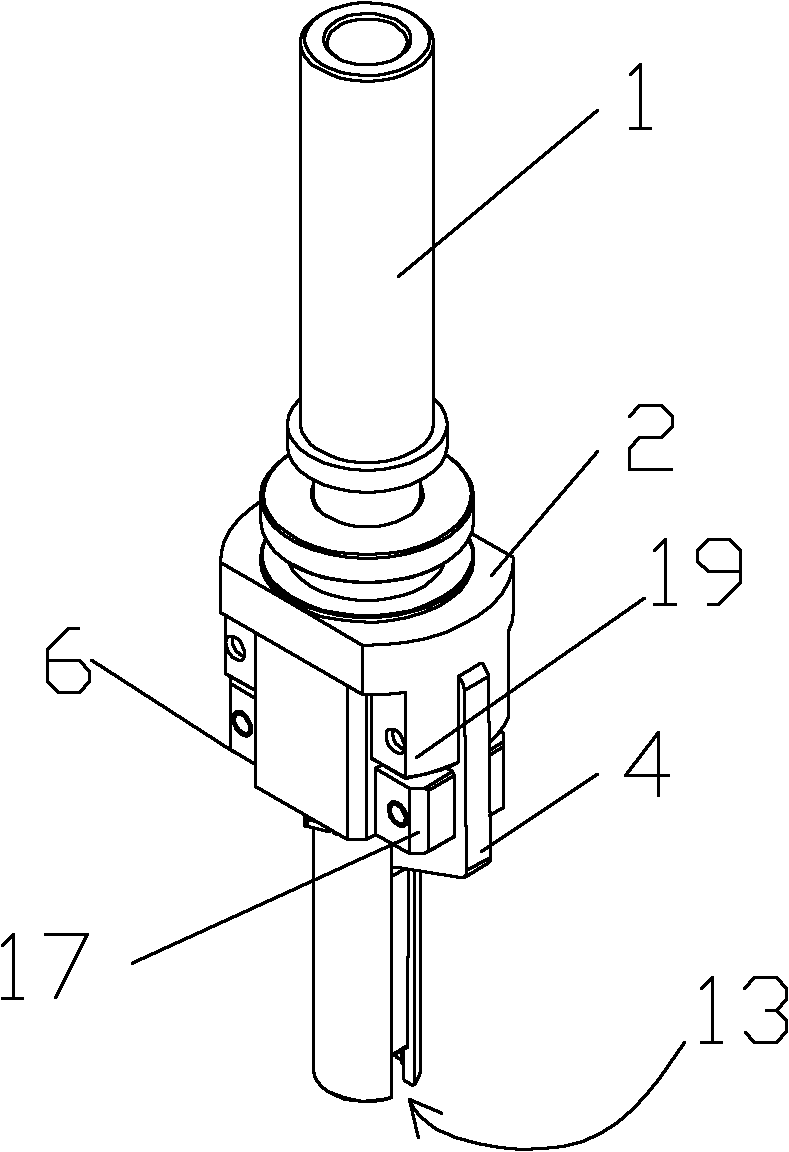
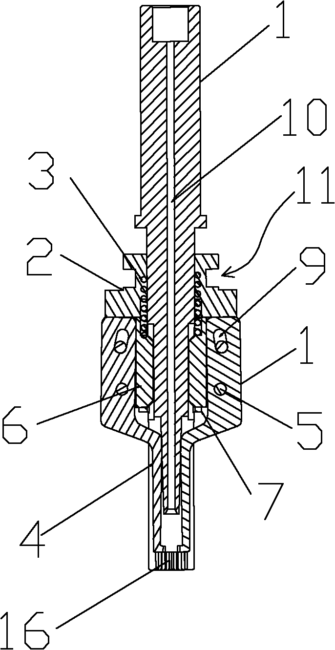
[0023] like Figure 1-3 As shown, a device for detecting and regulating the outlet gas flow of a lighter described in this embodiment includes a ventilation shaft 1, a clamp fixing seat 6 sleeved on the ventilation shaft 1 and a clamp adjusting member 2, and symmetrically arranged on both sides of the clamp fixing seat 6. The two splints 4, the clamp fixing seat 6 is fixedly installed on the ventilation shaft 1; the middle part of the splint 4 is pivotally connected to the lower part of the clamp fixing seat 6 through the positioning pin 18, and the upper part of the splint 4 has an upward and inward The adjustment hole 9 provided obliquely, a movable pin 5 runs through the adjustment hole 9 to connect the upper part of the splint to the clamp adjustment part 2, and the inner side of the bottom of the splint 4 forms a clamping opening 20; the center opening of the ventil...


PUM


Abstract

The invention relates to a device for detecting and adjusting gas outlet flow of a lighter, which solves the technical problem the adjusting nut of the lighter is difficult to adjust at present. The device for detecting and adjusting the gas outlet flow of the lighter comprises a ventilation shaft, a clamp fixing seat and a clamp adjustment piece which are sleeved on the ventilation shaft, and two splints symmetrically arranged on two sides of the clamp fixing seat; the clamp fixing seat is fixed on the ventilation shaft; the middle part of each splint is coupled to the lower part of the clamp fixing seat through a positioning pin; an adjustment hole is formed upward and inward on the upper part of each splint; a movable pin passes through the adjustment hole to connect the upper parts of the splints to the clamp adjustment piece; a clamp port is formed on the inner side of the bottom of each splint; a gas guide passage positioned above the clamp port is formed in the center of the ventilation shaft; and a flow detector is connected with the upper end of the gas guide passage. Compared with the conventional method for directly detecting the height of the flame, a method for adjusting the height of flame by detecting and adjusting the gas outlet flow of a gas outlet needle is more accurate and quicker.

Description

technical field [0001] The invention relates to a lighter detection and adjustment device, in particular to a lighter outlet gas flow detection and adjustment device. Background technique [0002] As a dangerous product, the flame height of the lighter is a necessary inspection item in the production process. According to the provisions of my country's entry-exit inspection and quarantine industry standards for the inspection of dangerous goods for export lighters, the qualification criteria for the flame height of lighters is: for lighters with flame height regulators, 98% of the test samples should meet the requirements. At the maximum flame position, the flame height is 150 mm or less within 5 seconds after ignition; when the flame height regulator is at the minimum flame position, the flame height is 50 mm or less within 5 seconds after ignition; For lighters, 98% of the test samples should meet the requirements. The flame height is 50 mm or less within 5 seconds after ig...

Claims


Application Information

Patent Timeline
Patent Type & Authority Applications(China)
IPC IPC(8): F23Q23/00
Inventor 黄新华
Owner XINHAI TECH GRP CO LTD
Learn More