Semi-physical simulation testing system and method for deep space autonomous navigation star sensor
A technology of semi-physical simulation and autonomous navigation, applied in the field of semi-physical simulation experiments of deep space autonomous navigation optical sensors, can solve the problems of not being used as an accuracy inspection instrument, the limitation of the emission accuracy of star simulation images, etc., and achieve high simulation accuracy and feasibility high effect
Active Publication Date: 2011-07-06
BEIJING INST OF CONTROL ENG
View PDF0 Cites 31 Cited by
- Summary
- Abstract
- Description
- Claims
- Application Information
AI Technical Summary
Problems solved by technology
All current liquid crystal light valve star simulators are limited by the accuracy of the star simulati
Method used
View moreImage
Smart ImageViewing Examples
Examples
 PUM
 Abstract
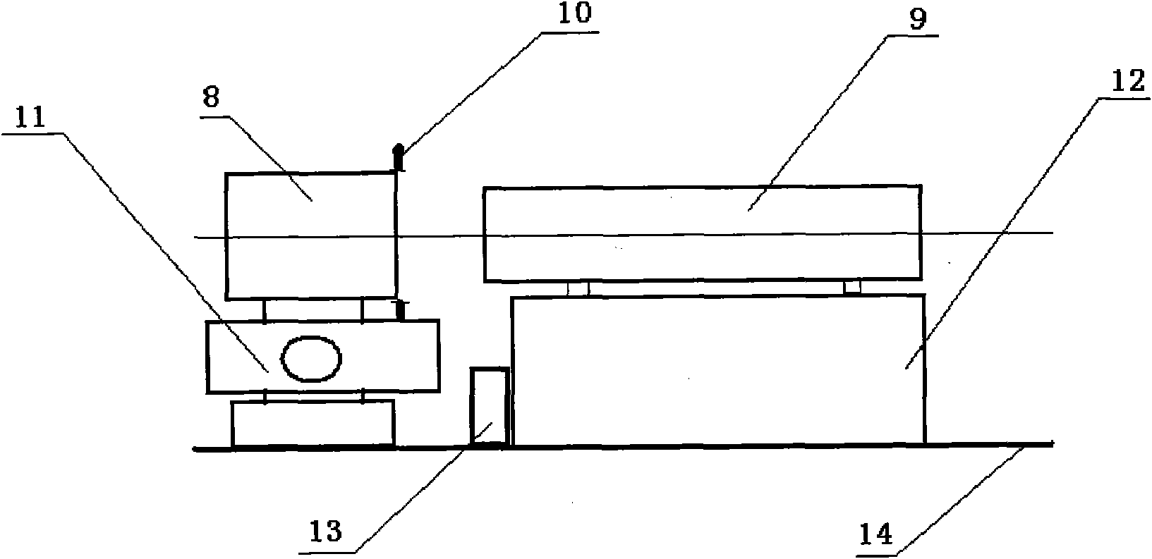
The invention provides a semi-physical simulation testing system for a deep space autonomous navigation star sensor and a method thereof. A star sensor simulator is placed on a similar support frame, and an autonomous navigation star sensor is fixed on a three-axis rate rotating table; the center of an entrance pupil of the autonomous navigation star sensor is arranged on a horizontal rotation central axis of the three-axis rate rotating table; an emergent pupil of the star sensor simulator is in butt joint with the entrance pupil of the autonomous navigation star sensor, and an optical axis of the star sensor simulator is superposed with the optical axis of the autonomous navigation star sensor; and the autonomous navigation star sensor, the three-axis rate rotating table and the star sensor simulator are all connected with a control and information processing computer. By adopting the system and the method, star simulation for the very high-precision star sensor for autonomous navigation of a minor planet can be solved, and the measurement precision of the star sensor and the autonomous navigation positioning precision are verified, thereby having broad application prospects for developing the deep space autonomous navigation sensors.
Description
technical field [0001] The invention relates to a semi-physical simulation test system and method of a deep-space autonomous navigation star sensor, which can be applied to a semi-physical simulation experiment of a deep-space autonomous navigation optical sensor. Background technique [0002] In the field of aerospace technology, the star sensor for deep space exploration optical navigation is a very high-precision star sensor, such as: its accuracy requires 0.5″, which is quite different from traditional star sensors, such as the entrance pupil diameter is about 150mm, The focal length is about 1000m, and the field of view is 1°~2°. Such a type of sensor mainly identifies the asteroids around the orbit of the cruise section of the deep space probe, and determines its angular position relative to the inertial space. The ephemeris data is used to calculate the position and velocity of the deep space probe relative to the earth-centered inertial coordinate system. [0003] A...
Claims
Login to View More Application Information
Patent Timeline
 IPC IPC(8): G01C25/00G01C21/24
Inventor 郝云彩王大轶黄翔宇
Owner BEIJING INST OF CONTROL ENG
Features
- R&D
- Intellectual Property
- Life Sciences
- Materials
- Tech Scout
- Unparalleled Data Quality
- Higher Quality Content
- 60% Fewer Hallucinations
Learn More Browse by: Latest US Patents, China's latest patents, Technical Efficacy Thesaurus, Application Domain, Technology Topic, Popular Technical Reports.
© 2025 PatSnap. All rights reserved.Legal|Privacy policy|Modern Slavery Act Transparency Statement|Sitemap|About US| Contact US: help@patsnap.com


