
Liquid crystal display device and driving method thereof

A technology of a liquid crystal display device and a driving method, which is applied to instruments, nonlinear optics, optics, etc., can solve the problems of high production cost and complicated process, achieve strong electric field strength, reduce process complexity, and ensure the time of grid scanning signal. Effect

Active Publication Date: 2012-05-09
SHANGHAI TIANMA MICRO ELECTRONICS CO LTD
View PDF3 Cites 0 Cited by
  • Summary
  • Abstract
  • Description
  • Claims
  • Application Information

AI Technical Summary

Problems solved by technology

[0005] The present invention solves the problem of high production cost and complicated process by making the liquid crystal molecules pre-tilt and needing to slit in the PVA process and make protrusions in the MVA process

Method used


Image

  • Liquid crystal display device and driving method thereof
  • Liquid crystal display device and driving method thereof
  • Liquid crystal display device and driving method thereof

Examples


Embodiment Construction

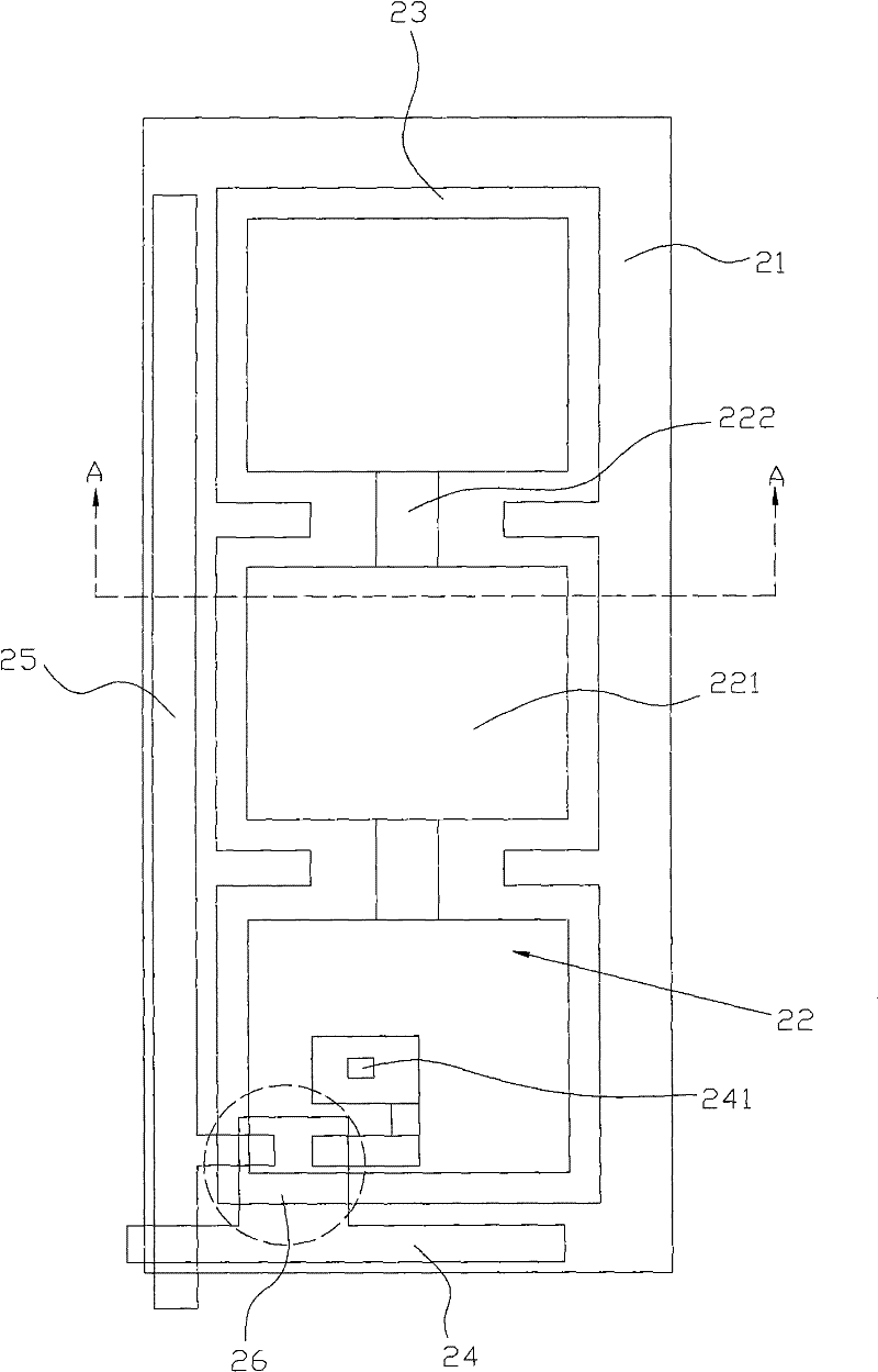
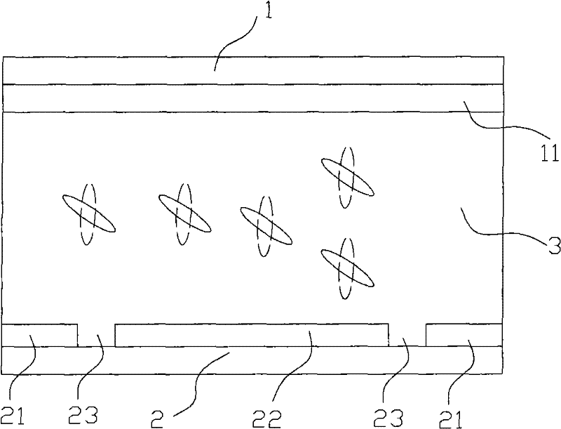
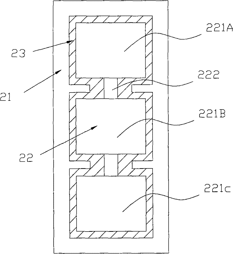
[0030] By forming the slit and the second common electrode in the process of forming the pixel electrode, when the driving signal is applied to the second common electrode, the liquid crystal molecules in the slit formed between the second common electrode and the pixel electrode are deflected in the pretilt direction The required electric field, in this way, the slit and the second common electrode can be formed by exposure and development together with the pixel electrode, and the electric field with the pretilt of the liquid crystal molecules can be obtained without adding any process.

[0031] See figure 1 with figure 2 The liquid crystal display device of the present invention includes a first substrate 1, a second substrate 2 and a liquid crystal layer 3.

[0032] A first common electrode 11 is provided on the first substrate 1.

[0033] A second common electrode 21 and a pixel electrode 22 are provided on the surface of the second substrate 2 directly facing the first common ...


PUM

PropertyMeasurementUnit
widthaaaaaaaaaa

Abstract

The invention relates to a liquid crystal display device and a driving method thereof. The liquid crystal display device comprises a first base plate, a second base plate and liquid crystal molecules positioned between the first base plate and the second base plate. A first common electrode is arranged on the first base plate. A pixel electrode and a second common electrode are arranged on the surface of the second base plate over the first common electrode; the second common electrode surrounds the pixel electrode; a slit is formed between the second common electrode and the pixel electrode;and when the second common electrode obtains a driving signal, an electric field for driving the liquid crystal molecules positioned in the slit to pre-tilt is formed between the second common electrode and the pixel electrode. As the slit, the second common electrode and the pixel electrode are all formed through exposure development, the electric field required for the pre-tilt of the liquid crystal molecules is obtained under the situation that no process is added; and compared with the conventional MVA (Machinery Vibration Analysis) method and the conventional PVA (Patterned Vertical Alignment) method, the production cost and the process complexity are reduced.

Description

Technical field [0001] The present invention relates to liquid crystal display technology, in particular to a vertically aligned liquid crystal display device and a driving method thereof. Background technique [0002] In the liquid crystal cell, the vertical alignment liquid crystal molecules are arranged vertically in the liquid crystal layer by the action of the surface riveting energy of the alignment film layer. When an electric field is applied to the indium tin oxide (ITO) plates on both sides of the liquid crystal layer, the liquid crystal molecules will be deflected under the action of the electric field. The arrangement of the polarizer and the backlight produces an optical path difference, and thus Display the image. However, if the bias electric field is uniform and the liquid crystal molecules cannot be pre-polarized, the deflection of the liquid crystal molecules is disorderly orientation. This disorderly orientation deflection not only requires a long response tim...

Claims


Application Information

Patent Timeline
Patent Type & Authority Patents(China)
IPC IPC(8): G02F1/1343G02F1/1362G02F1/1368
Inventor 霍思涛马骏任娇燕
Owner SHANGHAI TIANMA MICRO ELECTRONICS CO LTD
Learn More