Pole mechanical fixing structure of permanent magnet motor

A technology of mechanical fixation and permanent magnet motor, which is applied in the direction of magnetic circuit shape/style/structure, synchronous machine, electrical components, etc., can solve the problem of unreliable positioning of rotor magnetic poles, and achieve easy implementation, accurate installation and positioning accuracy, and reduce Effect of Installation Difficulty

Inactive Publication Date: 2011-07-20
HARBIN INST OF TECH
View PDF3 Cites 20 Cited by
  • Summary
  • Abstract
  • Description
  • Claims
  • Application Information

AI Technical Summary

Problems solved by technology

[0006] The purpose of the present invention is to solve the problem of unreliable positioning of the rotor magnetic poles of the inner rotor permanent magnet synchronous motor, and to provide a mechanical fixing structure for the magnetic poles of the permanent magnet motor

Method used


Image

  • Pole mechanical fixing structure of permanent magnet motor
  • Pole mechanical fixing structure of permanent magnet motor
  • Pole mechanical fixing structure of permanent magnet motor

Examples


specific Embodiment approach 1

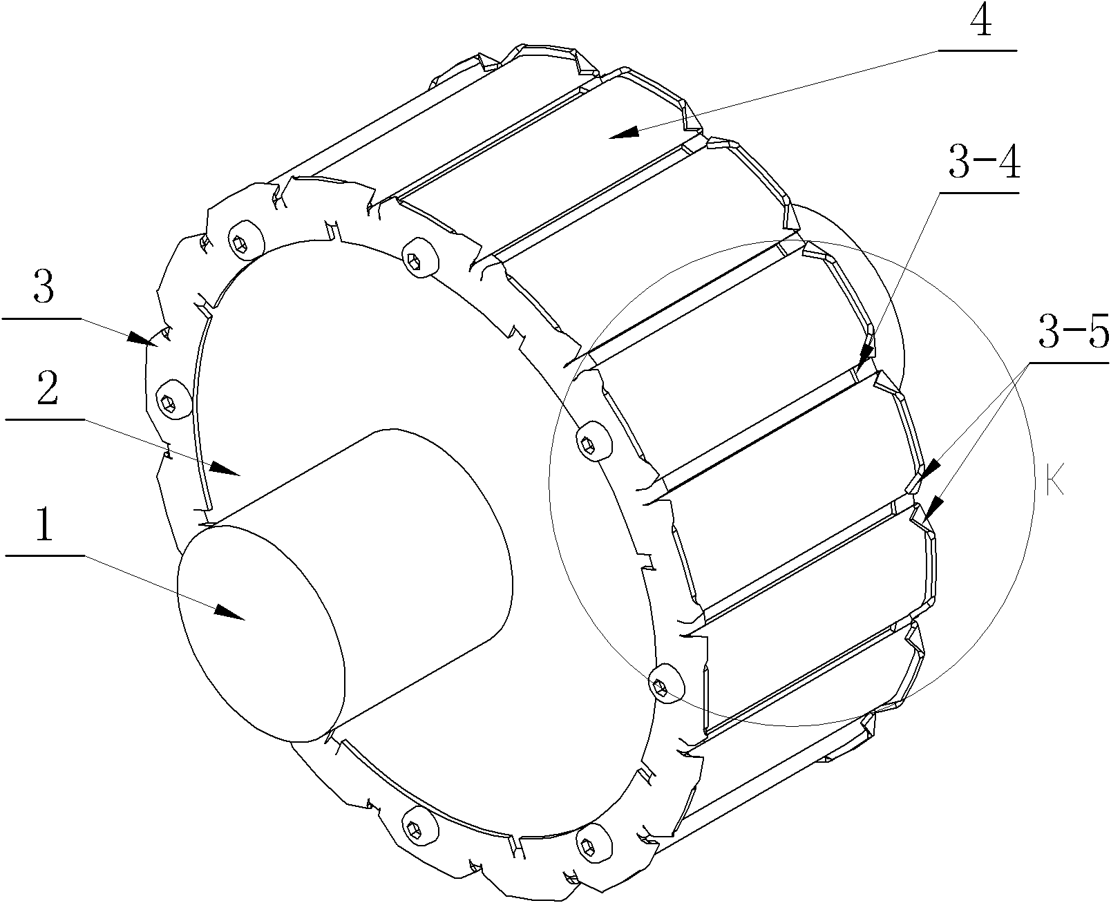
[0016] Specific implementation mode one: the following combination figure 1 and Figure 4 Describe this embodiment, this embodiment includes a rotating shaft 1 and a rotor yoke 2, the rotor yoke 2 is sleeved on the outer circular surface of the rotating shaft 1, it also includes two annular rotor pressure plates 3 and P magnetic poles 4,

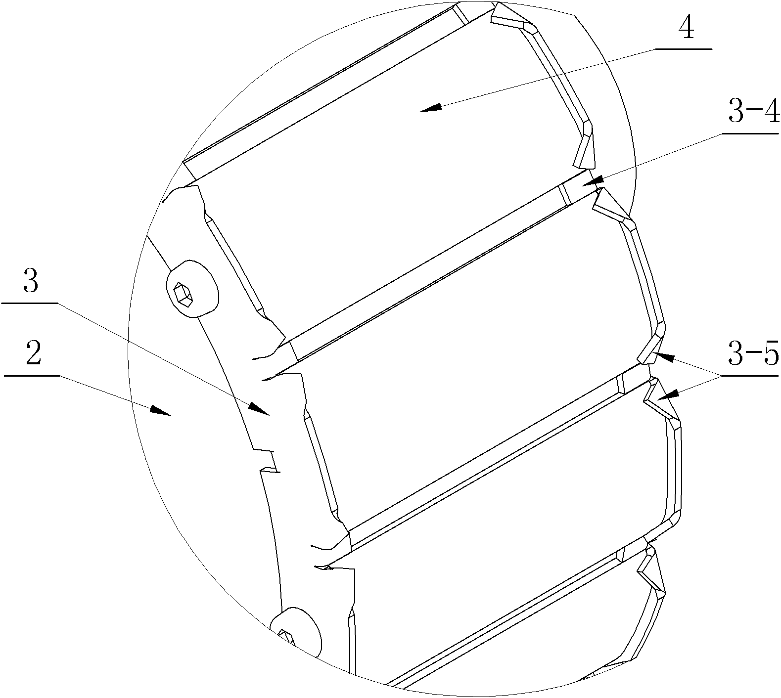
[0017] Two annular rotor pressure plates 3 are respectively fixedly connected to both ends of the rotor yoke 2, and form grooves with the outer surface of the rotor yoke 2, and P magnetic poles 4 are evenly distributed in the grooves along the circumferential direction of the rotor.

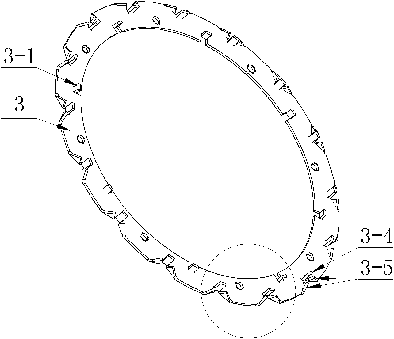
[0018] P number of limit pins 3-4 and P pair of convex pins 3-5 are respectively punched on the outer ring surface of each annular rotor pressure plate 3, and the P number of limit pins 3-4 are evenly distributed on the annular rotor pressure plate On the outer circumference of 3, the P limit pins 3-4 on the two annular rotor pressure plates 3 are arranged opp...

specific Embodiment approach 2

[0023] Specific implementation mode two: this implementation mode is a further description of implementation mode one,

[0024] The annular rotor pressure plate 3 is an integral structure or a spliced ​​structure.

[0025] Others are the same as the first embodiment.


PUM


Abstract

The invention discloses a pole mechanical fixing structure of a permanent magnet motor, belonging to the technical field of motors and solving the problem of unreliable positioning of a rotor magnetic pole of an inner rotor permanent magnet synchronous motor. A rotor yoke of the pole mechanical fixing structure is sleeved on the surface of an excircle of a rotating shaft, two circular rotor pressing plates are respectively fixedly connected to two ends of the rotor yoke and form a groove together with the outer surface of the rotor yoke, P magnetic poles are uniformly distributed in the groove along the circumference direction of the rotor, P limit pins and P pairs of convex pins are respectively punched in the surfaces of outer rings of the circular rotor pressing plates, the P limit pins are uniformly distributed on the outer circumferences of the circular rotor pressing plates, the P limit pins on the two circular rotor pressing plates are oppositely arranged, one pair of axially opposite limit pins is positioned between two adjacent magnetic poles and is in contact with the magnetic poles; and two sides of each limit pin are symmetrically provided with one pair of convex pins forming a V shape, and the convex pins are used for pressing and fixing end parts of the magnetic poles adjacent to the convex pins. The invention is suitable for positioning the magnetic poles of the inner rotor permanent magnet synchronous motor.

Description

technical field [0001] The invention relates to a magnetic pole mechanical fixing structure of a permanent magnet motor, which belongs to the technical field of motors. Background technique [0002] The permanent magnet synchronous motor and its servo system are widely used in the fields of industrial drive and servo control because of its small size, high efficiency and good dynamic response characteristics. From the perspective of motor structure, permanent magnet synchronous motors can be divided into two types: inner rotor structure and outer rotor structure. Compared with the outer rotor structure, the permanent magnet synchronous motor with the inner rotor structure has the following advantages: [0003] The winding and stator core of the inner rotor motor are installed on the outside of the rotor, so the heat dissipation surface area of ​​the motor is relatively large, and the thermal performance of the motor is better; the moment of inertia of the inner rotor motor ...

Claims


Application Information

Patent Timeline
Patent Type & Authority Applications(China)
IPC IPC(8): H02K21/00H02K1/28
Inventor 邹继斌江善林徐永向胡建辉
Owner HARBIN INST OF TECH
Why Eureka
Try Eureka