Drive device for a furniture flap

A driving device and a flip-cover technology, which are applied in the directions of the suspension device of the wing fan, the arrangement of the wing fan, the fastening device of the wing fan, etc., to achieve the effect of a compact structure.

Active Publication Date: 2011-07-20
JULIUS BLUM GMBH
View PDF7 Cites 6 Cited by
  • Summary
  • Abstract
  • Description
  • Claims
  • Application Information

AI Technical Summary

Problems solved by technology

Disadvantageous in this prior art is the fact that, when the flip is in the fully closed position, the ejection means must overcome the force of the spring means, which also makes it necessary to provide an ejection means of relatively large size

Method used


Image

  • Drive device for a furniture flap
  • Drive device for a furniture flap
  • Drive device for a furniture flap

Examples


Embodiment Construction

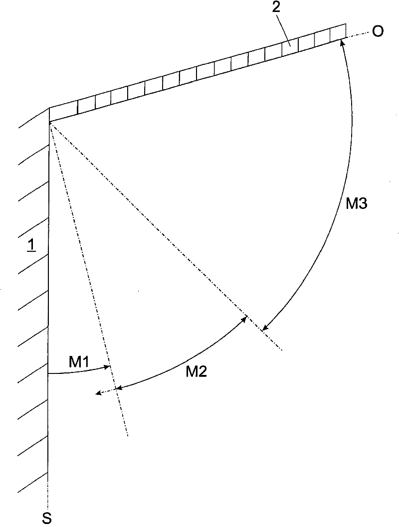
[0024] figure 1 A schematic diagram showing the different opening angle ranges M1 , M2 and M3 of the flap 2 which can be moved up relative to the furniture body 1 . In this illustration, the flip 2 is in the fully open position. The flap 2 is mounted so that it can be adjusted between a vertical position (indicated by a vertical axis S) and an upwardly movable open position (axis O) closing the cabinet compartment in the furniture body 1 . In order to push the flap 2 out of the closed position, an ejection device (not shown) is provided, and a spring device (likewise not shown) is provided to compensate or at least partially assist the opening movement. Starting from the fully closed position (vertical axis S) of the flap 2, said flap is moved by means of the push-out device in the direction of the open position through a first opening angle range M1 in which the spring device is substantially No force is applied to flip 2. In this way, the flap 2 can be moved out of the cl...


PUM


Abstract

Drive device for a flap (2) of a piece of furniture (3), having at least one actuating arm (6) which is, or can be, activated by a spring device (4) and is intended for moving the flap (2), and having a pushing-out device (5), via which the flap (2) can be moved from the closed position, in the direction of the open position, over a first opening-angle range (M1), wherein the spring device (4) exerts substantially no force on the flap (2) in the first opening-angle range (M1), and the spring device (4) moves the flap (2) in the opening direction only in a second opening-angle range (M2), wherein the second opening-angle range (M2) adjoins the first opening-angle range (M1) or, at most, slightly overlaps the same.

Description

technical field [0001] The invention relates to a drive device for a flap of furniture, having at least one adjusting arm which is loaded or can be loaded by a spring means and has an ejection device for moving the flap, by means of which The device enables the flap to move from the closed position toward the open position through a first range of opening angles. [0002] Furthermore, the invention relates to a piece of furniture having a drive device of the type described. Background technique [0003] Such an actuation device is known, for example, from the applicant's German utility model application DE 20 2006 000 535 U1, in which an ejection device with a touch-latch function is provided for ejecting the flap from the closed end position. Furthermore, an additional spring device is provided which takes over the task of compensating the weight of the flap. However, the spring device also exerts a greater closing force on the flap, so that after the dead center position...

Claims


Application Information

Patent Timeline
Patent Type & Authority Applications(China)
IPC IPC(8): E05F1/10E06B3/48E05D15/26E05B17/00
CPCE05Y2201/22E05Y2800/00E05Y2201/232E05C19/165E05F1/1041E05Y2201/424E05Y2201/244E05D11/1064E05Y2900/00E05Y2900/20E05F1/1058E05D15/262E05Y2201/416E05Y2800/11E05Y2201/618Y10T74/20341
Inventor C·奥曼W·伯勒
Owner JULIUS BLUM GMBH
Why Eureka
Try Eureka