
Surge protector having a thermal separating device

A technology for protecting equipment and overvoltage, applied in the direction of overvoltage protection resistors, circuits, resistors, etc., can solve the problem of unilateral separation of bridge parts, and achieve the effect of safe separation

Active Publication Date: 2011-07-20
デーンエスエープルスツェオーカーゲー
View PDF4 Cites 12 Cited by
  • Summary
  • Abstract
  • Description
  • Claims
  • Application Information

AI Technical Summary

Problems solved by technology

In addition, there is the risk of unintentional one-sided detachment of the bridge

Method used


Image

  • Surge protector having a thermal separating device
  • Surge protector having a thermal separating device
  • Surge protector having a thermal separating device

Examples


Embodiment Construction

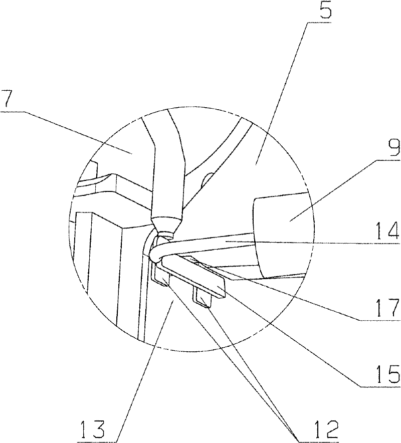
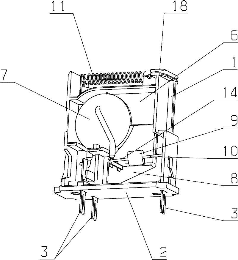
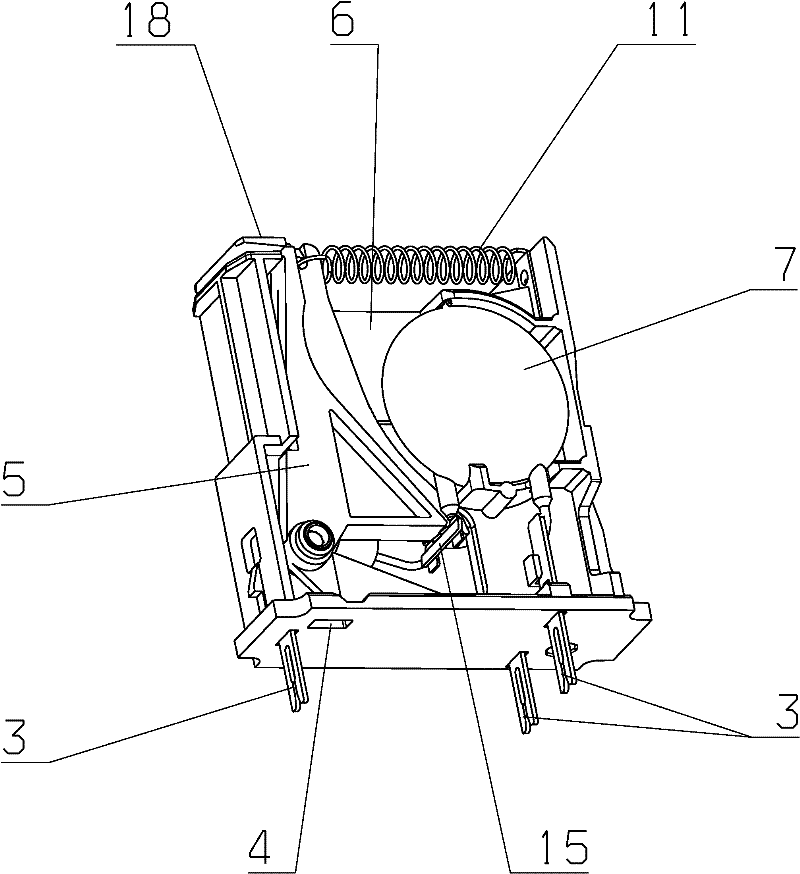
[0038] The overvoltage protection device shown in the figure comprises a plastic molding 1 of the main body, which is surrounded by a cover, not shown in the figure.

[0039] There are openings for the plug contacts 3 in the bottom region 2 of the plastic molding 1 of the base body. Furthermore, there is a notch 4 in order to be able to produce ( ) communication connection.

[0040] The base plastic molded part 1 has a partition wall 6 .

[0041] The left side and the right side of the partition wall 6 respectively have a disk-shaped piezoresistor 7 which has two connecting arms respectively.

[0042] The first connection arm of each varistor 7 is connected to the plug contact 3 .

[0043] The second connecting arm protrudes into the free space 8 inside the base plastic molded part 1 .

[0044] Furthermore, there is a gas arrester 9 . The connecting line 10 of the gas arrester 9 leads to one of the plug contacts 3 . The piezoresistor 7 and the gas arrester 9 are wired in ...


PUM


Abstract

The invention relates to a surge protector having a thermal separating device and an error display, and at least two first protection elements, particularly disk-shaped varistors (7), and at least one second protection element, particularly a gas arrester (9), wherein the first and the at least one second protection elements are switched in a Y arrangement, further comprising a device housing foraccommodating the protection elements, and a means (11) for the mechanical biasing of the thermal separating device, wherein the thermal separating device has a low-melting solder, and the first protection elements (7) are disposed in the device housing such that a connection arm of a protection element (7) is positioned opposite the connection arm of the further protection element (7) at a distance, and the thermal separating device is predominantly positioned in the distance space (13); formed in such a manner. According to the invention, a connection arm of the second protection element (9) directly bypasses said connection arms (12) of the first protection elements (7) in the distance space in a solder-contacted manner, wherein a finger (16) of a mechanically biased separating block (5) acts upon the bypass connection arm (15) such that in the event of an overload the bypass connection arm (15) is spatially placed at a distance to the connection arms (12) of the first protection elements (7).

Description

technical field [0001] The invention relates to an overvoltage protection device according to the preamble of claim 1, said overvoltage protection device comprising: a thermal disconnection device and a fault indicator; and at least two first protection elements, in particular disc-shaped a varistor; and at least one second protective element, in particular a gas arrester, wherein the first protective element and the at least one second protective element are connected in a Y-shaped arrangement; furthermore, the overvoltage protection device Also comprising a device housing or support part for receiving a protective element and means for mechanically pretensioning said thermal separation device; wherein said thermal separation device has a low-melting solder or similar medium, and said first The protective elements are arranged in such a way that a respective connecting arm of one protective element lies at a distance from the connecting arm of the other protective element, an...

Claims


Application Information

Patent Timeline
Patent Type & Authority Applications(China)
IPC IPC(8): H01C7/12
CPCH01C7/126
Inventor S·路德维希R·道姆G·维特曼F·格克
Owner デーンエスエープルスツェオーカーゲー
Learn More