Nonvolatile status indicator switch

a status indicator switch, non-volatile technology, applied in the direction of relays, emergency protective arrangements for limiting excess voltage/current, instruments, etc., can solve the problems of net current imbalance, aircraft electrical system faults can be dangerous, aircraft electrical system faults occur in aircraft electrical systems

a status indicator switch, non-volatile technology, applied in the direction of relays, emergency protective arrangements for limiting excess voltage/current, instruments, etc., can solve the problems of net current imbalance, aircraft electrical system faults can be dangerous, aircraft electrical system faults occur in aircraft electrical systems

US20090174981A1Inactive Publication Date: 2009-07-09LEACH INT

Image

  • Nonvolatile status indicator switch
  • Nonvolatile status indicator switch
  • Nonvolatile status indicator switch

Examples


Embodiment Construction

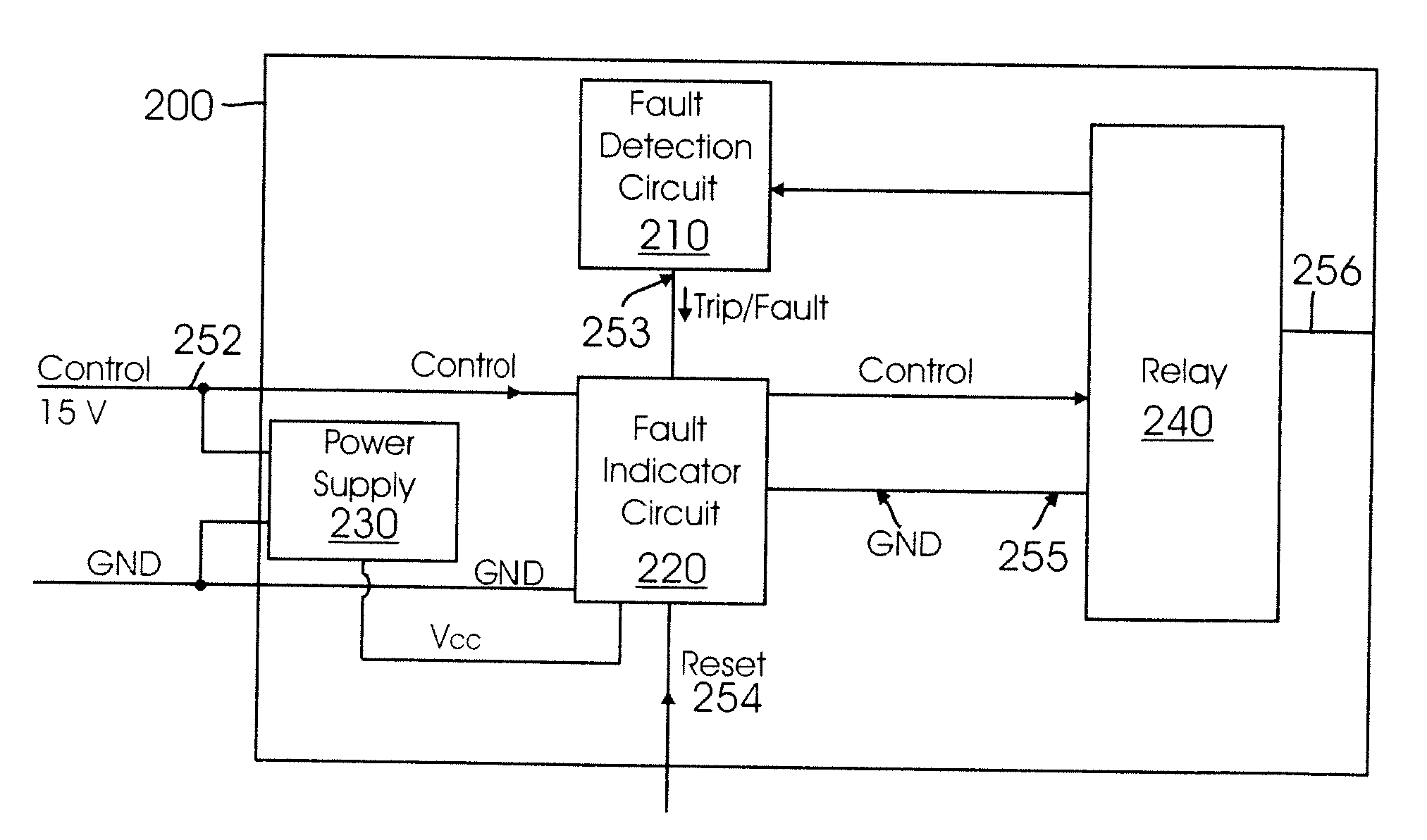
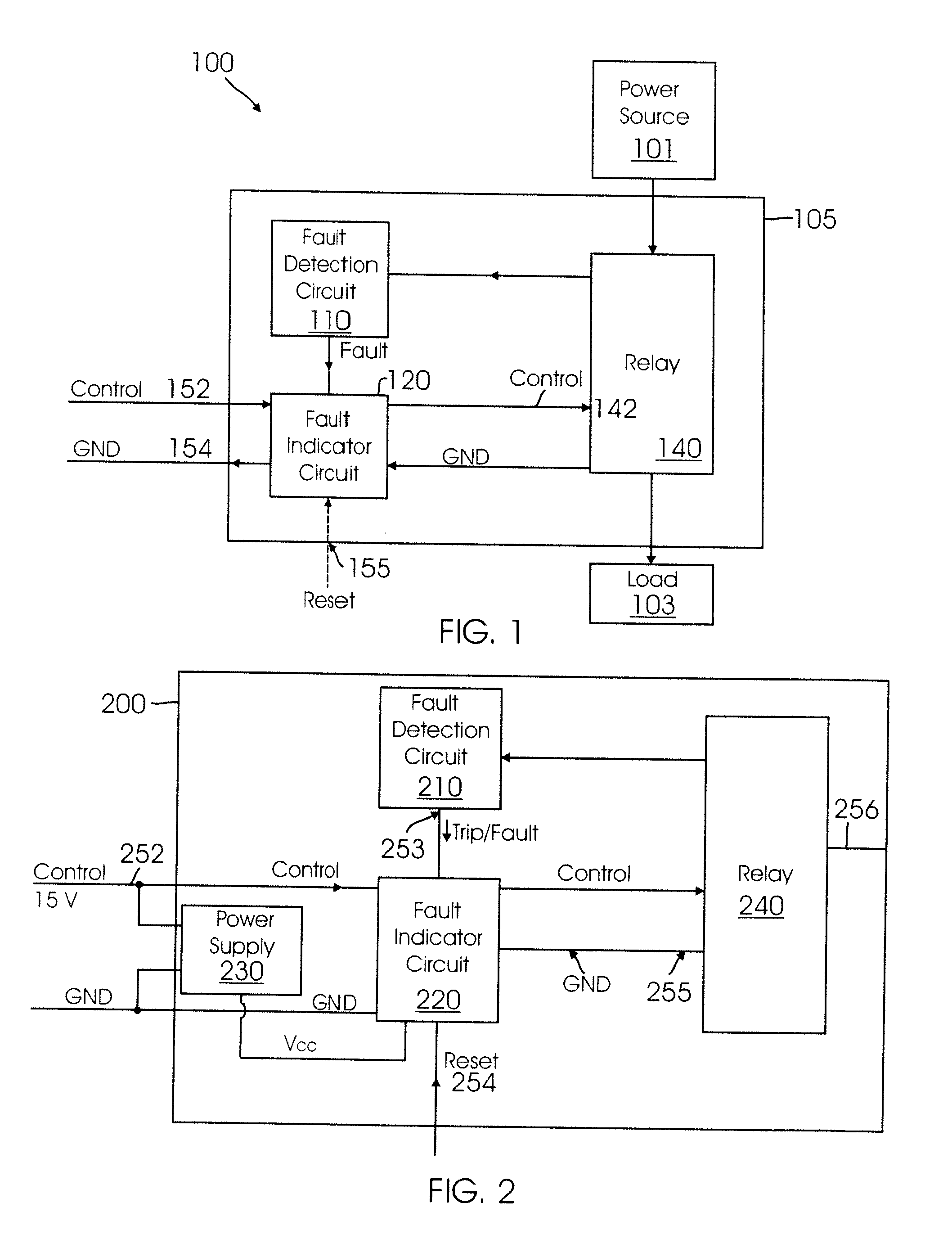
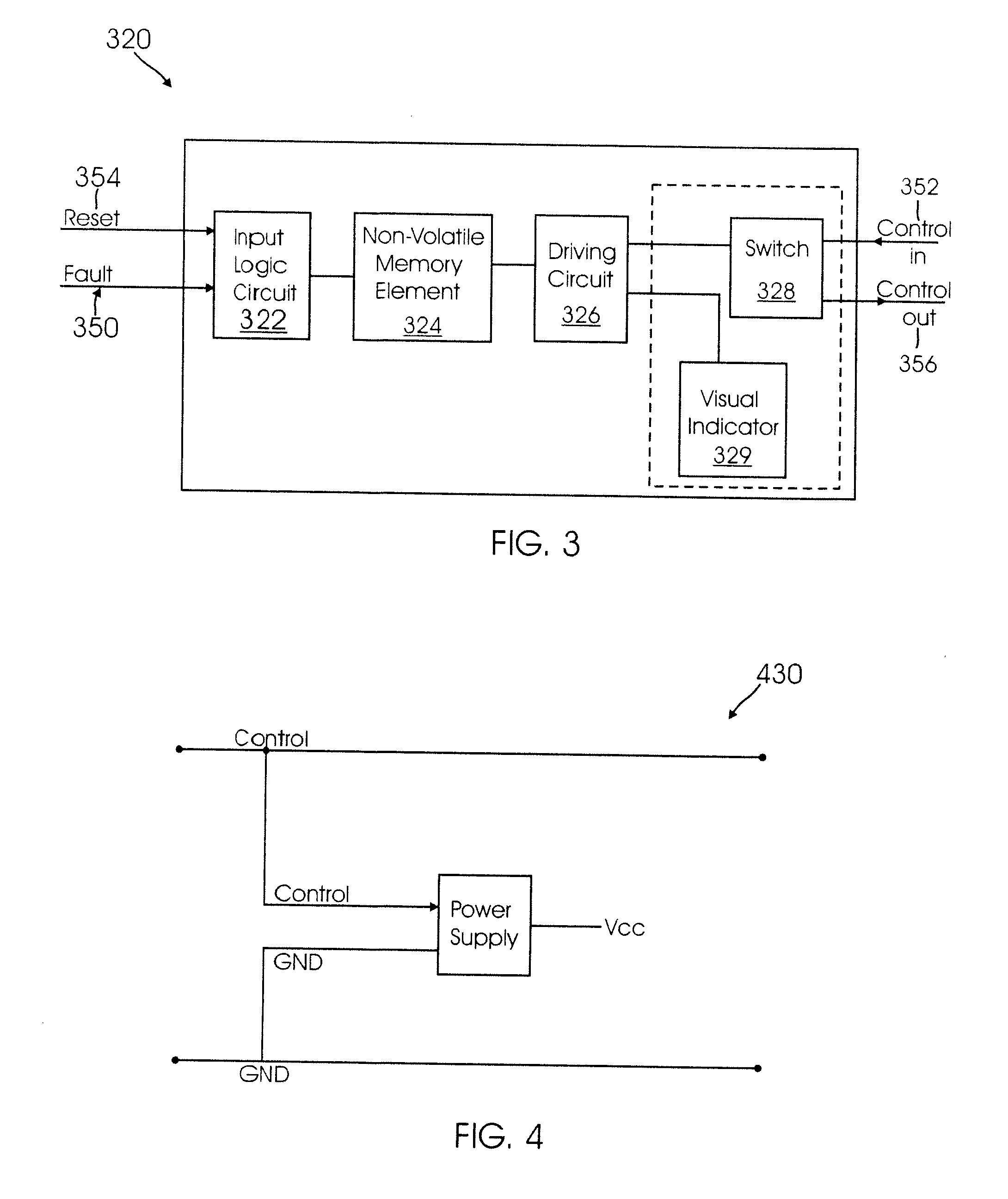
[0025]Referring now to the drawings, embodiments of fault indicator circuits in accordance with the present invention are illustrated that can be included in a relay for use in an aircraft electrical system. The fault indicator circuits can be used to interrupt a control signal provided to the relay in the event that a fault condition is detected. The interruption of the control signal can cause the relay to disconnect power from a load. In several embodiments of the present invention, the fault indicator circuit includes a nonvolatile memory for storing information indicative of the existence of a fault. When power is removed from the fault indicator, the nonvolatile memory preserves the fault status information. When power is restored to the relay, the fault indicator circuit can prevent the relay from being activated until the fault is cleared and the monitored device is manually reset.

[0026]In a number of embodiments, the fault indicator circuit is implemented using solid state ...


PUM


Abstract

A non-volatile status indicator switch is provided. In one embodiment, the invention relates to an aircraft electrical system including a fault detection circuit coupled to a relay, and a fault indicator circuit coupled to the fault detection circuit and to a control input of the relay, wherein the fault indicator circuit includes a nonvolatile memory element, wherein the fault detection circuit is configured to detect a fault and to provide a signal indicative of the fault to the fault indicator circuit, and wherein the fault indicator circuit is configured to respond to the signal indicative of the fault by providing a predetermined control signal to the relay and by storing information indicative of the detection of the fault in the nonvolatile memory element.

Description

BACKGROUND OF THE INVENTION[0001]The present invention relates generally to the use of relays in aircraft electrical systems and more particularly to systems and methods for saving and indicating the status of a detected fault in the relays.[0002]The primary functions of an aircraft electrical system are to generate, regulate and distribute electrical power throughout the aircraft. There are several different power sources on an aircraft that are used to supply power to aircraft electrical systems. These power sources can include engine driven AC generators, auxiliary power units, external power and ram air turbines. Aircraft electrical components operate on many different voltages levels using both AC and DC. However, most of the aircraft systems use 115V AC at 400 Hz or 28V DC. Further, 26V AC is also used in some aircraft for lighting purposes. DC power is generally provided by “self-exciting” generators containing electromagnets, where the power is generated by a commutator whic...

Claims


Application Information

Patent Timeline
09 Jul 2009
Publication
US20090174981A1
IPC
H02H3/04; G08B21/00
CPC
G08B3/10; H01H50/08; H01H47/002
Inventors
MALLON, ROBERT C.; KHAN, IMTIAZ