Method for operating a piston expander of a steam motor

一种膨胀器、活塞式的技术,应用在使活塞式膨胀器运行的一种方法领域,能够解决有害空间、不允许新鲜蒸气等问题,达到效率高的效果

Active Publication Date: 2011-08-10
MAN SONDERFAHRZEUGE AG
View PDF13 Cites 7 Cited by
  • Summary
  • Abstract
  • Description
  • Claims
  • Application Information

AI Technical Summary

Problems solved by technology

Therefore there is often the following problem: the harmful space does not allow sufficient fresh steam all at once

Method used


Image

  • Method for operating a piston expander of a steam motor
  • Method for operating a piston expander of a steam motor
  • Method for operating a piston expander of a steam motor

Examples


Embodiment Construction

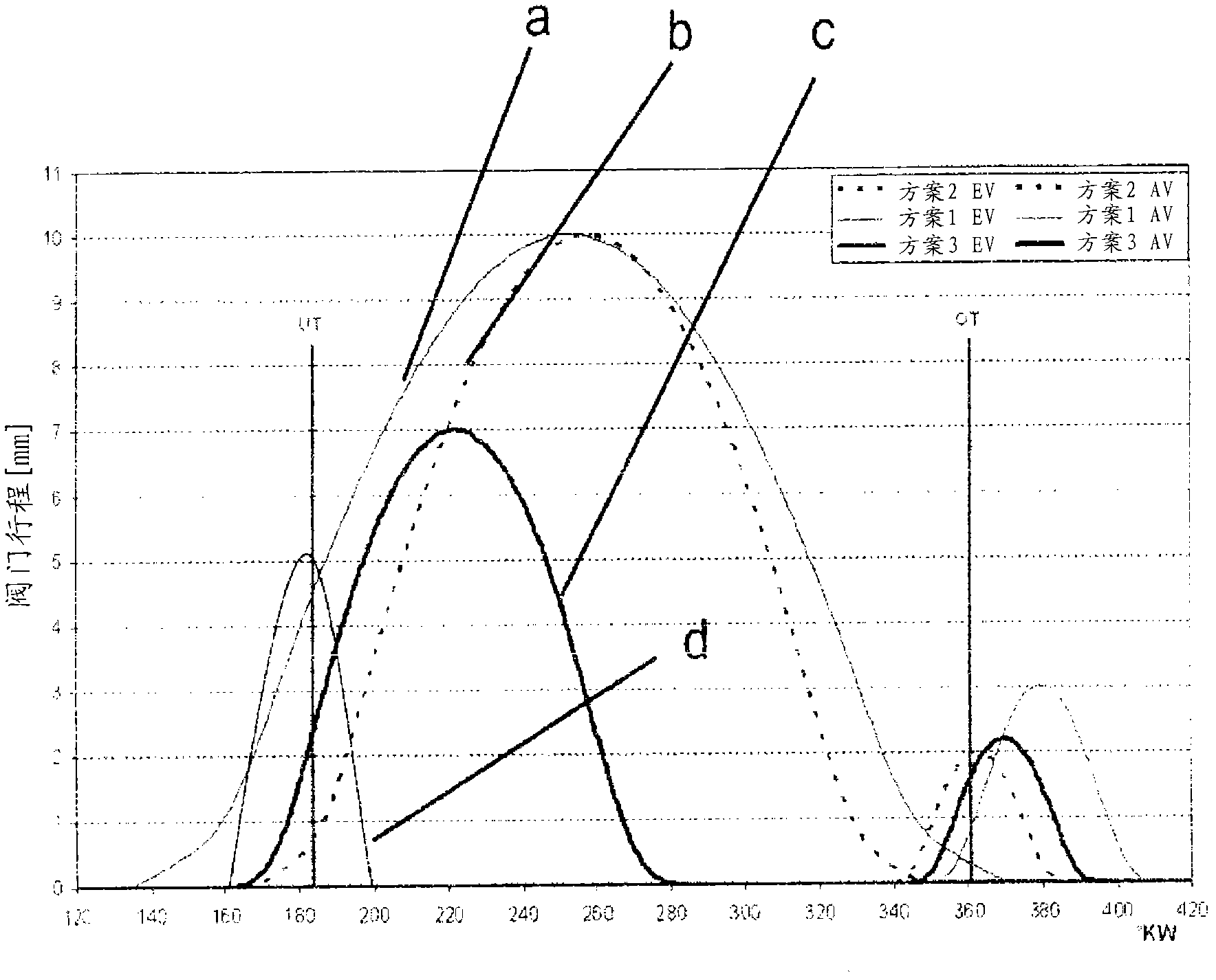
[0023] figure 1 Shows the stroke of the valve in an exhaust port of a cylinder of a steam expander. Here, the function curves a, b, and c formed by the valves correspond to the crankshaft angles when different valves are controlled. The attainment of the bottom dead center and the top dead center are each illustrated by vertical lines at approximately 182° or 361° crankshaft angle. The thin function curve a and the dotted curve b each represent the exhaust valve travel in the known standard method. The third function curve in thick lines shows the valve stroke of the outlet valve when using the method according to the invention for opening and closing the outlet valve.

[0024]It can be clearly seen that with a valve stroke of the exhaust valve according to the function curves a, b, the exhaust valve is opened in a relatively wide range between the upper dead center and the lower dead center of the piston. The opening of the vent valve according to the invention is represen...


PUM


Abstract

A method of operating a piston expander, including introducing live steam into a cylinder space via an inlet valve; expanding the live steam during a power stroke in which a piston moves from an upper dead center position to a lower dead center position; opening an outlet opening as soon as the piston is in the region of the lower dead center position; after the piston reaches the lower dead center position, conveying the expanded steam out of the outlet opening and into a steam discharge; and subsequently closing the outlet opening before the piston in an exhaust stroke reaches the lower dead center position.

Description

technical field [0001] The invention relates to a method of operating a piston expander, wherein live steam is fed from a steam feed device through an inlet valve into a cylinder chamber, the live steam entering the cylinder chamber is driven by the piston from the top dead center during the working stroke. The movement to the bottom dead center is decompressed, and the depressurized steam is introduced into the steam discharge system through a closable exhaust port after reaching the bottom dead center. Background technique [0002] In order to be able to save fuel, especially in mobile internal combustion engines, such as, for example, automotive internal combustion engines, two technical approaches are currently preferred. In addition to the use of various hybrid concepts, heat recovery systems are known, the former being provided primarily for urban and distributed traffic, where braking and acceleration processes occur, and the latter using internal combustion The wast...

Claims


Application Information

Patent Timeline
Patent Type & Authority Applications(China)
IPC IPC(8): F01B25/02
CPCF01K23/065Y02E20/18F01B17/04F01K7/00F01K7/36
Inventor R 阿姆鲍尔
Owner MAN SONDERFAHRZEUGE AG
Why Eureka
Try Eureka