Double-sided-scanning type irradiance testing jig

A double-sided scanning and irradiance technology, which is applied in the field of irradiance test racks, can solve the problems of inability to accurately determine the UV irradiance of the UV aging test box, low reliability of test results, and low measurement accuracy.

Inactive Publication Date: 2011-08-10
EGING PHOTOVOLTAIC TECHNOLOGY CO LTD
View PDF0 Cites 10 Cited by
  • Summary
  • Abstract
  • Description
  • Claims
  • Application Information

AI Technical Summary

Problems solved by technology

[0003] Before performing the light test on the battery components, the irradiance of ultraviolet light in the UV aging test box must be corrected first, in order to ensure that the irradiance of ultraviolet light of the components during the test meets the requirements of the International Electrotechnical Commission (IEC) standard The current general method is to place a UV irradiance test frame in the UV aging test box. The UV irradiance test frame simulates the light conditions of the battery components to be tested in the UV aging test box, and its size is the same as that of the battery to be tested. The components are equivalent, and the erection position of the ultraviolet irradiance test frame is the same as that of the battery component to be tested. Multiple irradiance probes are used to determine the irradiance of ultraviolet light in the UV aging test chamber through these fixed irradiance probes. This kind of ultraviolet irradiance test frame has a simple and practical structure, but its measurement accuracy is low and cannot Accurately determine the irradiance of ultraviolet light in the ultraviolet aging test chamber, the customer's trust in this test result is not high, so it is urgent to improve it so that it can more accurately reflect the ultraviolet light in the ultraviolet aging test chamber irradiance

Method used


Image

  • Double-sided-scanning type irradiance testing jig
  • Double-sided-scanning type irradiance testing jig
  • Double-sided-scanning type irradiance testing jig

Examples


Embodiment 1

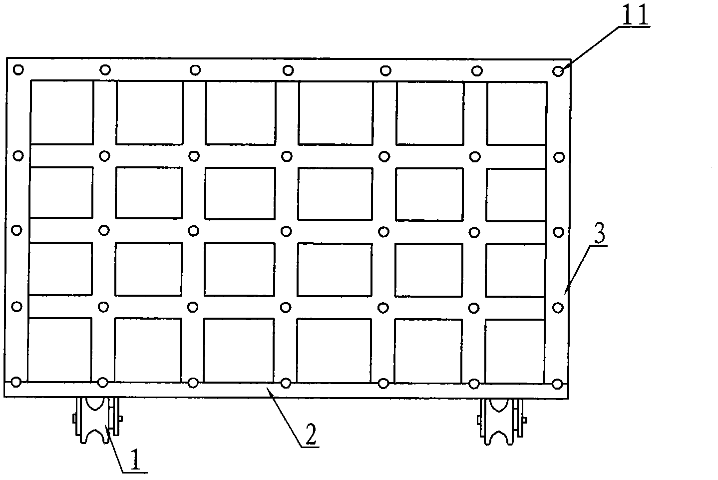
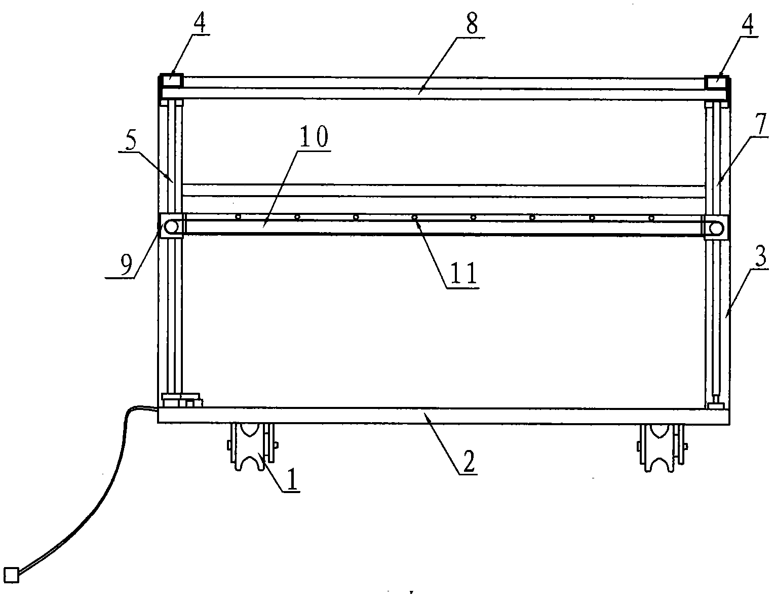
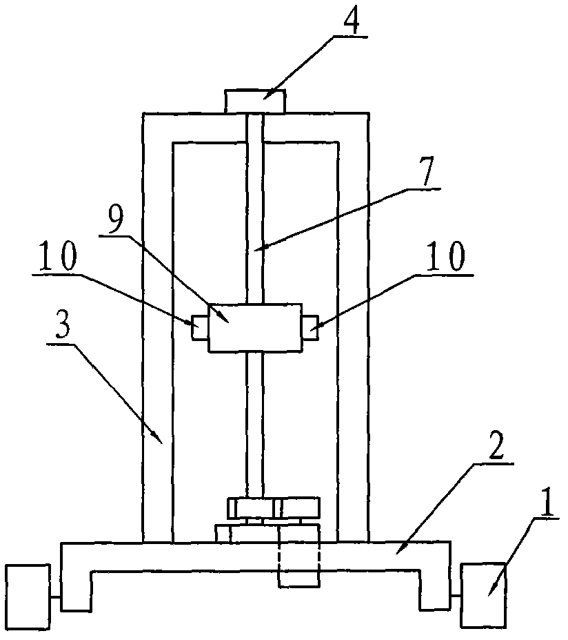
[0015] Embodiment 1: the double-sided scanning irradiance test frame, such as figure 2 , image 3 with Figure 4 As shown, it includes roller 1, bottom frame 2, vertical frame 3, bearing seat 4, left screw rod 5, timing pulley 6, right screw rod 7, timing belt 8, mobile installation block 9, horizontal rod 10, spoke The illuminance probe 11 and the lifting motor 12, the vertical frame 3 are fixed on the upper end surface of the bottom frame 2, and four rollers 1 are installed on the lower end surface of the bottom frame 2. Corresponding guide groove, the two ends of left screw mandrel 5 and right screw mandrel 7 are all fixed on the vertical frame 3 by bearing seat 4, and left screw mandrel 5 and right screw mandrel 7 are parallel, and perpendicular to bottom frame 2, on the left The upper ends of the screw mandrel 5 and the right screw mandrel 7 are equipped with a synchronous pulley 6 at the same height, and the two synchronous pulleys 6 are connected by a synchronous bel...

Embodiment 2

[0016] Embodiment 2: In Embodiment 1, the lifting motor 12 drives the right screw mandrel 7 to rotate through the driving gear 13 and the driven gear 14 .


PUM


Abstract

The invention discloses a double-sided-scanning type irradiance testing jig, which comprises a roller, a base frame, a vertical frame, two screw rods, an upper belt wheel, a synchronous belt, mobile mounting blocks, horizontal levers, irradiance probes and an elevation motor, wherein the vertical frame is fixed on an upper end face of the base frame, two ends of the two screw rods are respectively and fixedly on the vertical frame through a bearing block and are vertical to the base frame, the upper ends of the two screw rods are connected by the synchronous belt, the mobile mounting blocks are rotatably arranged on the two screw rods, two sides of the two mobile mounting blocks are respectively provided with one horizontal lever, a plurality of irradiance probes are arranged on each horizontal lever at equal intervals, and the screw rods are driven by the elevation motor. During testing, the horizontal levers can be used for very accurately measuring the irradiance of ultraviolet light in an ultraviolet ageing test chamber by vertical scanning once, the higher the mounting density of the irradiance probes on the horizontal levers is, the more accurate the measured data is, and the two double-sided-scanning type irradiance testing jig can be used for obviously improving the testing precision of the irradiance of the ultraviolet ageing test chamber.

Description

Technical field: [0001] The invention relates to ultraviolet aging test equipment for solar battery components, in particular to an irradiance test frame for an ultraviolet aging test box for solar battery components. Background technique: [0002] Solar cell modules are placed outdoors for a long time so that the cells absorb sunlight and convert it into electrical energy for transmission to the grid. However, the ultraviolet rays in the sun will age the packaging materials of the components, thereby reducing the service life of the components. In order to simulate the real situation and test the performance of the packaging materials of the solar cell components, according to the International Electrotechnical Commission (IEC) standard, the solar cell components are in the Ultraviolet (UV) irradiation pretreatment must be carried out before the thermal cycle / wet freeze cycle test to determine the UV attenuation of the relevant materials and adhesive connections. For this ...

Claims


Application Information

Patent Timeline
Patent Type & Authority Applications(China)
IPC IPC(8): G01J1/04G01N17/00
Inventor 刘志刚
Owner EGING PHOTOVOLTAIC TECHNOLOGY CO LTD
Why Eureka
Try Eureka