Parallel flow-combining machine

A technology of conveyor belts and baffles, applied in the direction of conveyors, conveyor objects, mechanical conveyors, etc., can solve the problems of large area for conveying and confluence, and achieve fast confluence speed, small area and large confluence capacity. Effect

Inactive Publication Date: 2011-08-17
YUNNAN KUNMING SHIPBUILDING DESIGN & RESEARCH INSTITUTE
View PDF4 Cites 3 Cited by
  • Summary
  • Abstract
  • Description
  • Claims
  • Application Information

AI Technical Summary

Problems solved by technology

[0003] The purpose of the present invention is to solve the deficiencies of the prior art, to provide a simple and efficient merging mechanism to improve the merging a

Method used


Image

  • Parallel flow-combining machine
  • Parallel flow-combining machine
  • Parallel flow-combining machine

Examples


Embodiment Construction

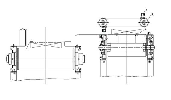
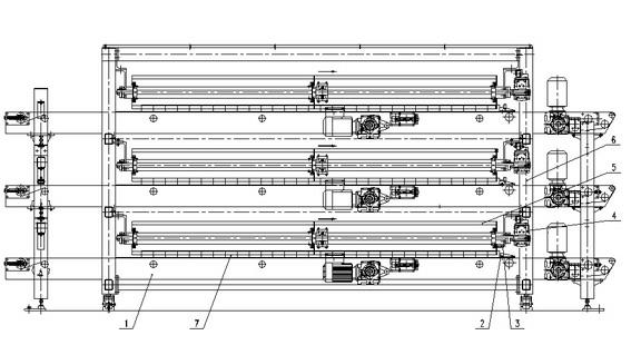
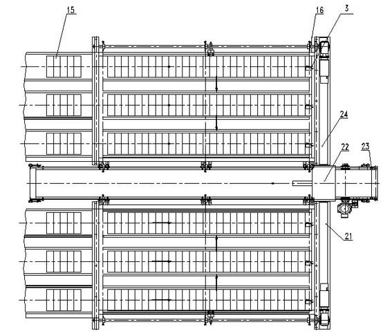
[0016] Such as figure 2 , image 3 , Figure 4 Shown, the present invention is made up of left confluence device 24, right confluence device 21, center belt machine 14 and electric device etc. Comprising a left confluence device 24 and a right confluence device 21 installed on the legs 6, a central belt conveyor 14 with a feeding direction perpendicular to the discharge direction of the confluence device and docked with the confluence device is arranged between the left confluence device and the right confluence device; Both the left confluence device and the right confluence device include at least two layers of confluence mechanisms 4 and are arranged symmetrically, and the number of layers of the central belt machine is the same as that of the confluence device. In this embodiment, the confluence mechanism and the central belt machine are all provided with three layers. At least two confluence channels are provided on each confluence mechanism of each confluence device,...


PUM


Abstract

The invention discloses a parallel flow-combining machine. The parallel flow-combining machine comprises a left flow-combining device (24) and a right flow-combining device (25), wherein central tape units (14) of which the material feeding directions are vertical to the material discharging directions of the flow-combining devices is arranged between the left flow-combining device and the right flow-combining device; both of the left flow-combining device and the right flow-combining device comprise at least two layers of flow-combining mechanisms (4) which are symmetrically arranged; the number of the central tape units is the same as the layer number of the flow-combining devices; at least two flow-combining passages are arranged on each layer of flow-combining mechanism of each flow-combining device; each flow-combining mechanism comprises a conveyer belt (1) and a circulating chain (8) which is positioned above the conveyer belt and is provided with a continuous lifting lever (5); the moving direction of the circulating chain is vertical to the conveying direction of the conveyer belt; shaping baffle plates (22) are arranged at the material discharging ends of the central tape units; a baffle plate (2) and an in-position photoelectric detection switch (3) are arranged at the tail end of the conveyer belt of each flow-combining mechanism; and photoelectric detection switches (23) are arranged on the parts, at the rear ends of the shaping baffle plates (22), of the central tape units. Through the parallel flow-combining machine, the strip cigarette flow-combining ability can be improved and the aim of high-speed sorting is fulfilled.

Description

technical field [0001] The invention relates to the technical field of high-speed sorting equipment for cigarette rods. technical background [0002] In the technical field of high-speed sorting of cigarettes, the existing merging devices are usually as figure 1 As shown, it is a single-channel structure with a small number of merging flows and a slow merging speed, and the plane is arranged at right angles to the conveying and merging flow, and the cigarette c enters the downstream device d through the fast dial b on the sprocket a, and the downstream device d then The cigarette c that was dialed over was transported away. This confluence device is relatively simple, has a single action, occupies a large area, and has a relatively small processing capacity. Moreover, the stroke of this merging device is too long, the processing time is long, and each station is in a waiting state for a long time, resulting in a longer merging cycle, which is difficult to meet the needs of...

Claims


Application Information

Patent Timeline
IPC IPC(8): B65B35/44B65G37/00B65G47/70
Inventor 张勇闵定勇王学兴连小嫚李晓景袁召云杨孝杨俊雄
Owner YUNNAN KUNMING SHIPBUILDING DESIGN & RESEARCH INSTITUTE
Why Eureka
Try Eureka