
Binder of energized components in an ophthalmic lens

An ophthalmic lens and electrification technology, which is applied in the direction of electrical components, electric solid devices, glasses/goggles, etc., and can solve the problem of lack of electrification mechanism for devices

Inactive Publication Date: 2011-08-17
JOHNSON & JOHNSON VISION CARE INC
View PDF7 Cites 21 Cited by
  • Summary
  • Abstract
  • Description
  • Claims
  • Application Information

AI Technical Summary

Problems solved by technology

However, such devices lack an independent power-up mechanism
While wires can be connected between the lens and the battery to power the semiconductor device, there are theories that the device could be powered wirelessly, although no such wireless powering mechanism is currently available

Method used


Image

  • Binder of energized components in an ophthalmic lens
  • Binder of energized components in an ophthalmic lens
  • Binder of energized components in an ophthalmic lens

Examples


Embodiment Construction

[0018] Glossary

[0019] In this detailed description and claims directed to the invention, a number of terms may be used to which the following definitions apply:

[0020] Energized: The state of being able to supply current or having electrical energy stored within it.

[0021] Energized Ophthalmic Lenses: An energized ophthalmic lens is an ophthalmic lens that has an energy source added or embedded in the resulting lens.

[0022] Energy source: A device capable of supplying energy or placing an ophthalmic lens in an energized state.

[0023] Energy Harvester: A device capable of extracting energy from the environment and converting it into electricity.

[0024] Lens: As used herein, "lens" refers to any ophthalmic device that resides in or on the eye. These devices may provide optical correction or may be cosmetic. For example, the term lens may refer to contact lenses, intraocular lenses, overlay lenses, ocular implants, optical implants or other similar devices. I...


PUM


Abstract

The invention discloses methods and apparatus for providing an ophthalmic lens with an energy source incorporated therein.

Description

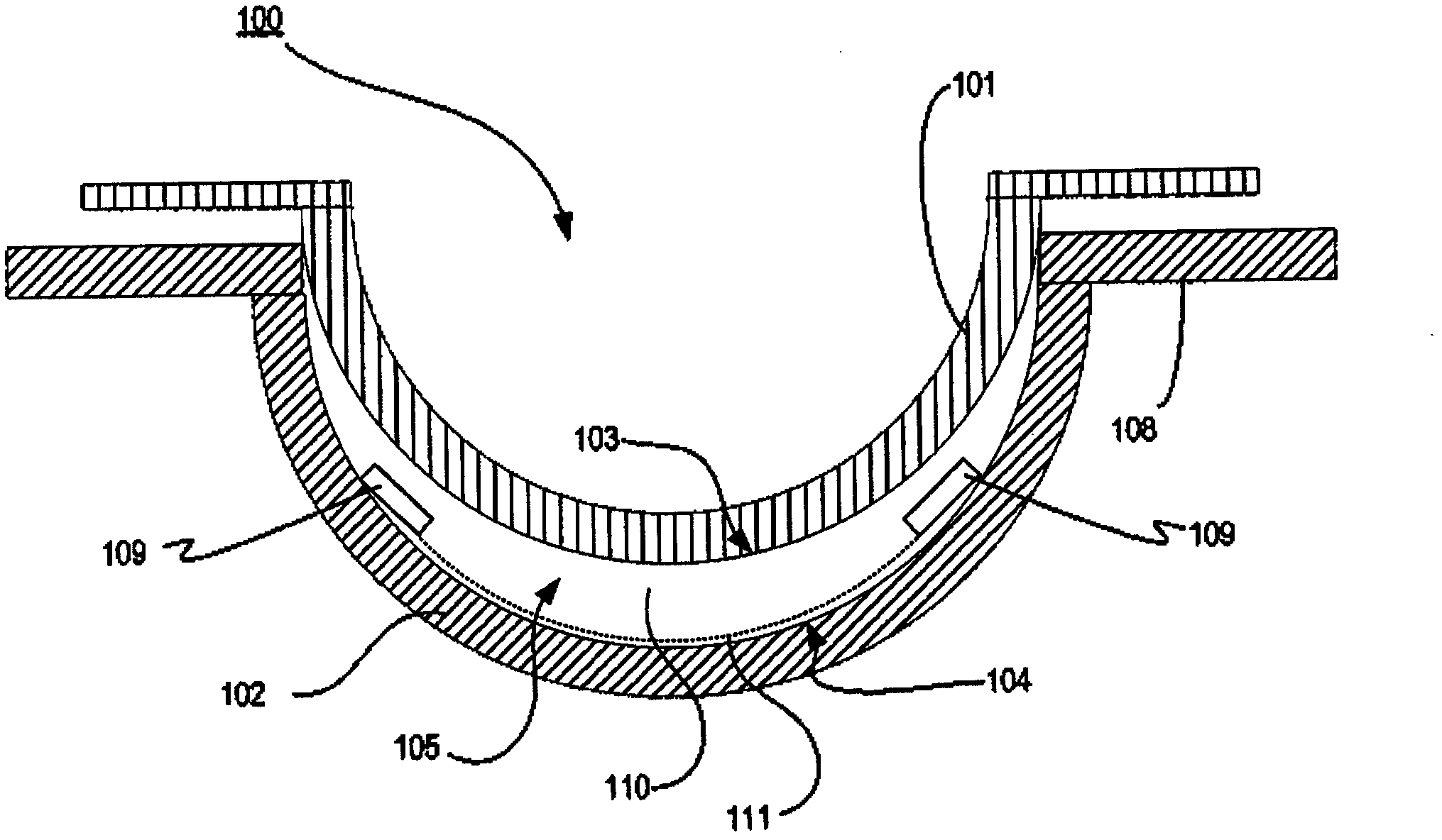
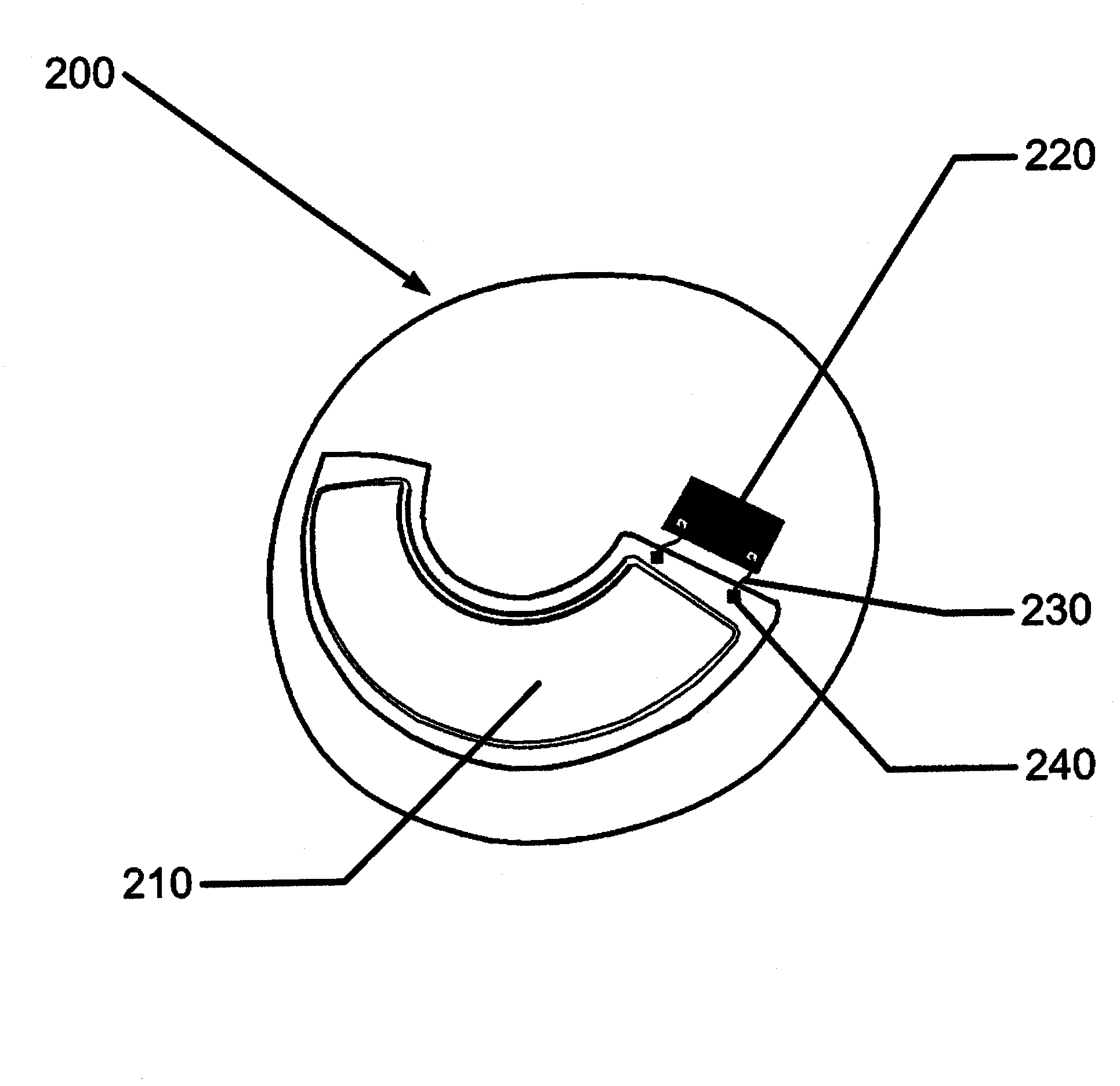
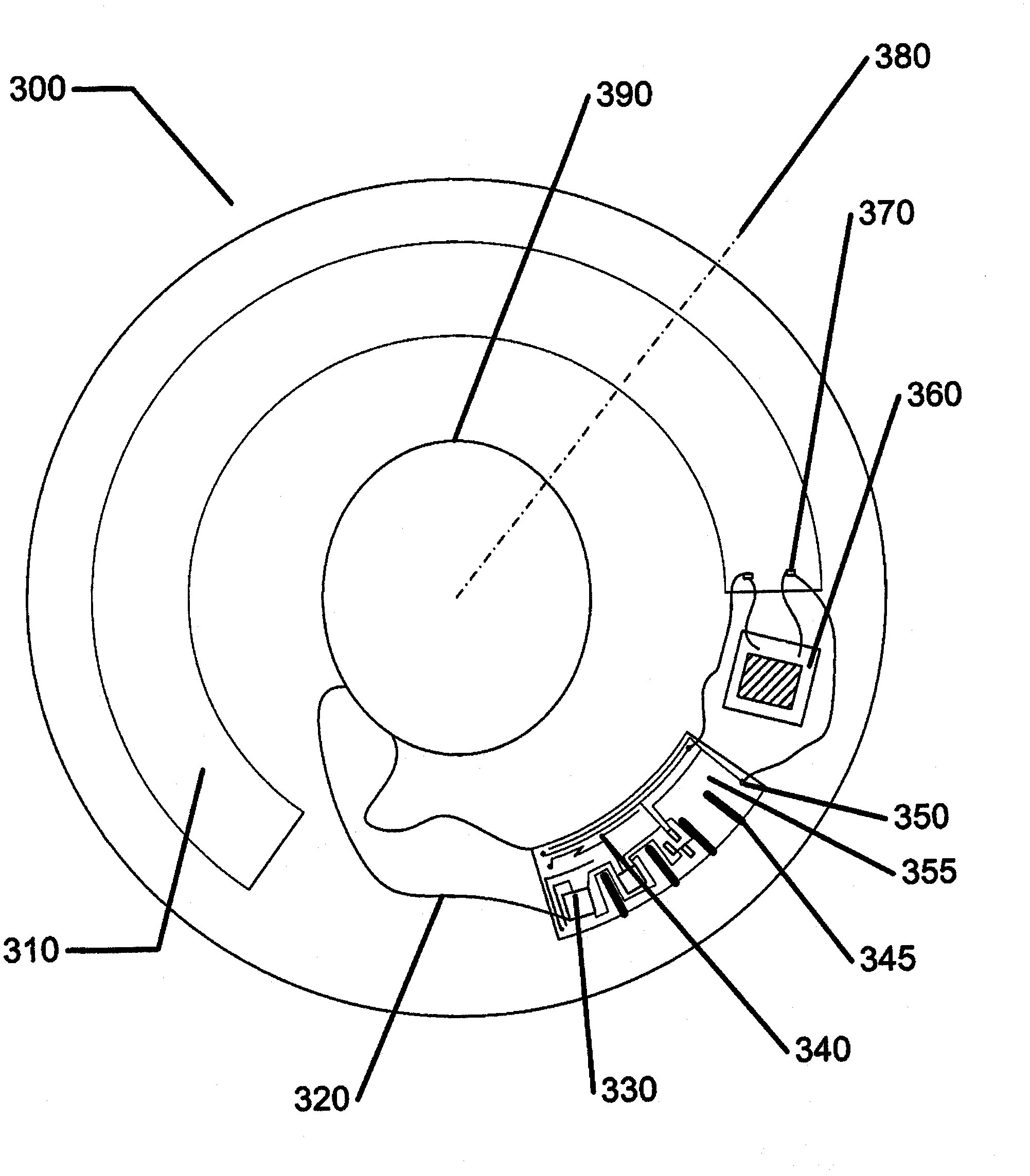
[0001] Related Patent Applications [0002] This patent application claims priority to U.S. Provisional Patent Application No. 61 / 192,765, entitled "Energized Ophthalmic lens," filed September 22, 2008 and also claims a continuation-in-part of an application filed in 2009 The priority of US Patent Application 12 / 557,016, entitled "Energized Ophthalmic Lenses," filed September 10, the respective contents of which are hereby incorporated by reference. technical field [0003] The present invention relates to methods and apparatus for forming energized ophthalmic lenses, and more particularly, in some embodiments, to bonding one or more energy sources and components within ophthalmic lens molds to facilitate the formation of energized ophthalmic lenses method. Background technique [0004] Traditionally, ophthalmic devices such as contact lenses, intraocular lenses or punctal plugs have included biocompatible devices with corrective, cosmetic or therapeutic properties. For ex...

Claims


Application Information

Patent Timeline
IPC IPC(8): B29D11/00
CPCG02C7/083B29D11/00038G02C7/04B29D11/00826H01L2224/48091G02C11/10H01L2924/00014
Inventor R·B·皮尤D·B·奥茨F·A·弗利特施
Owner JOHNSON & JOHNSON VISION CARE INC
Learn More