
Method for diagnostic marker development

A technology for identifying markers and markers, which is applied in the field of identifying markers and can solve problems such as linkage barriers and DNA polymorphism difficulties.

Inactive Publication Date: 2014-01-29
KEYGENE NV
View PDF13 Cites 0 Cited by
  • Summary
  • Abstract
  • Description
  • Claims
  • Application Information

AI Technical Summary

Problems solved by technology

However, for crops with a very narrow genetic base of cultivars, it is difficult to identify any DNA polymorphisms that serve as initiation points for DNA marker formation, despite relatively large linkage barriers

Method used


Image

  • Method for diagnostic marker development
  • Method for diagnostic marker development
  • Method for diagnostic marker development

Examples


Embodiment

[0067] The principle of the current invention is to generate markers in the vicinity of the target trait. These markers are unique within the germplasm and were designed based on the sequence knowledge available for the selected DNA segment.

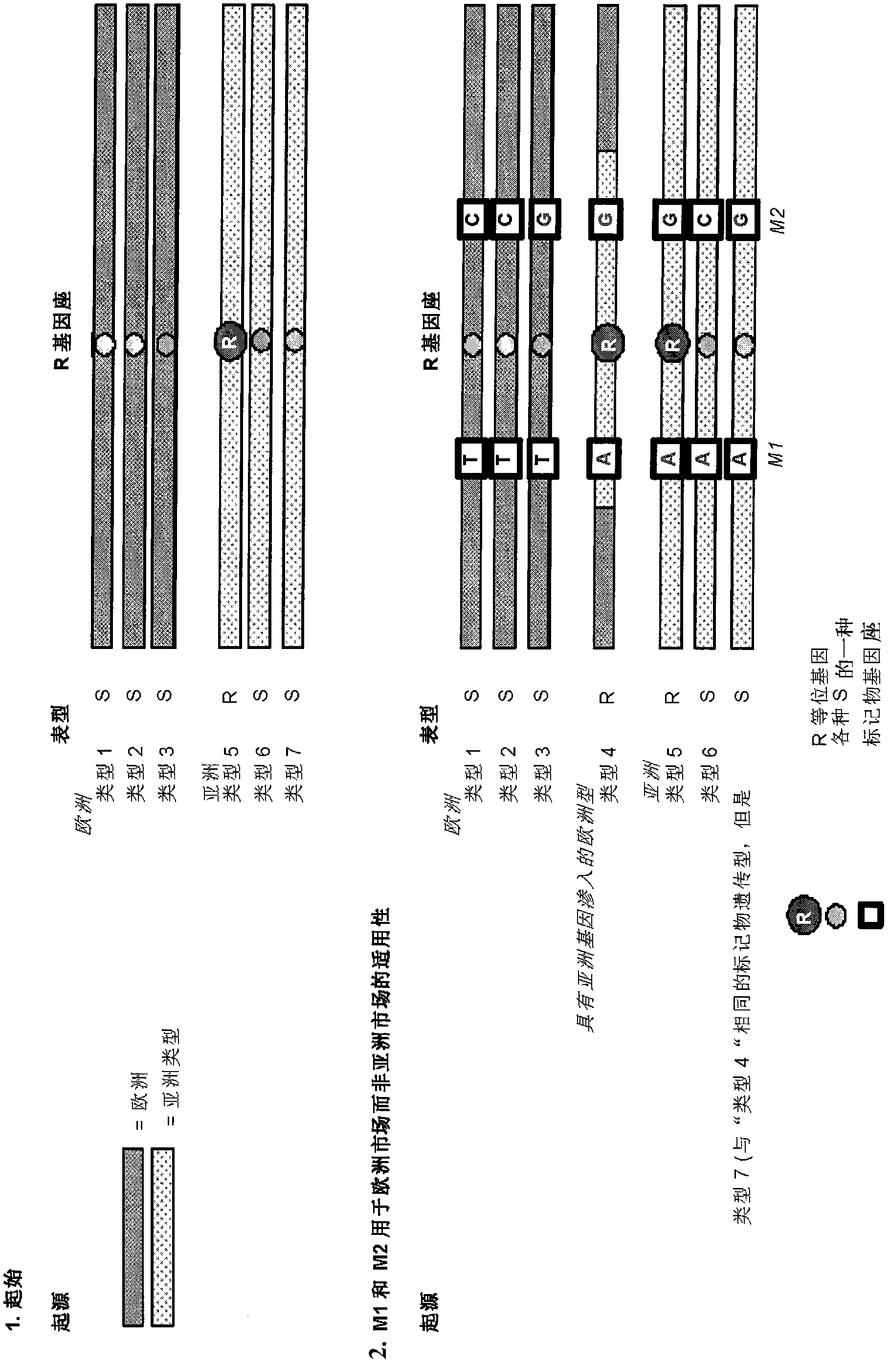
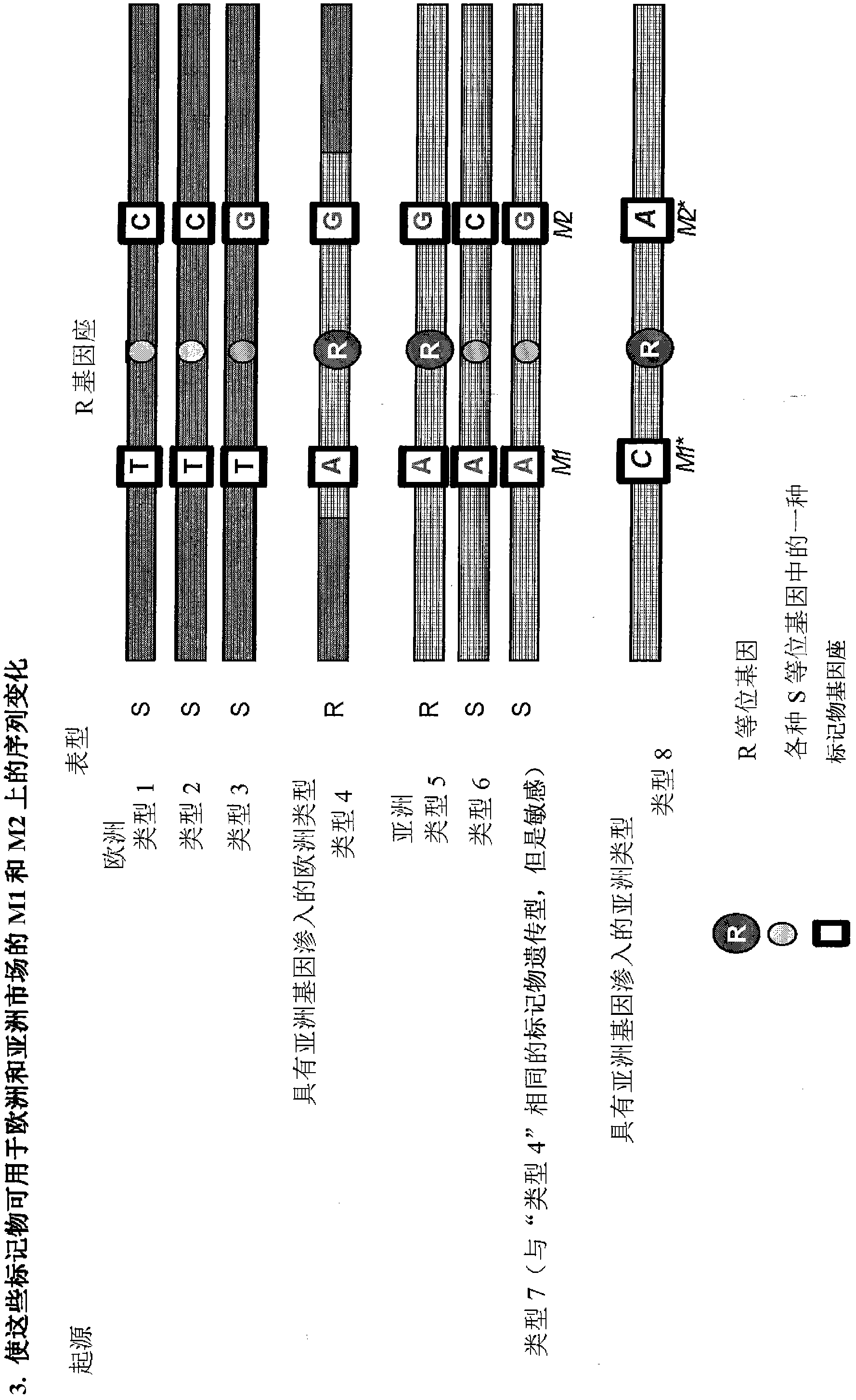
[0068] As a first example describing the starting environment, STS markers M1 and M2 have been developed for the disease resistance trait R obtained from a wild ancestor of the crop of interest ( figure 1 ). This disease resistance trait R was derived from an Asian accession ("Type 5") and has been introgressed into a cultivated European background, resulting in the European breeding line "Type 4". STS markers M1 and M2 were formed based on the sequence of marker loci M1 and M2 flanking the R gene. Only marker M1 has a good predictive value for trait R in segments of the target crops commercially available in Europe. Linkage disorders containing Asian resistant haplotypes were relatively large in European backgrounds.

[0069] Weak ...


PUM


Abstract

The invention relates to a method for the generation of unique molecular markers in existing breeding material by selecting a marker associated with a trait, identifying the existing variation at the nucleotide level within a set of markers within a germplasm and introducing a selectable marker by the introduction of one or more nucleotides at positions in a constant region of the marker by targeted nucleotide exchange.

Description

technical field [0001] The present invention relates to a method for forming molecular markers in living organisms, especially identification markers. The method also relates to the introduction of a selectable marker into the germplasm of an organism, and the use of the marker eg in the process of plant breeding. Background technique [0002] For decades, DNA marker technology has been dramatically increasing the efficiency of plant breeding through selection based on easy experimental markers rather than often difficult selection for phenotypic traits. However, the formation of such identification markers and the efficiency with which they are used are often laborious and time-consuming processes. First, the formation of the identification marker follows a process initiated by the following procedure [0003] 1) Draw the genetic position map of the genes under the target traits, [0004] 2) Identify flanking markers, [0005] 3) finely map the genes through the identif...

Claims


Application Information

Patent Timeline
Patent Type & Authority Patents(China)
IPC IPC(8): C12N15/10C12Q1/68
CPCC12Q1/6827C12Q2535/131C12Q1/6811
Inventor J·N·A·M·鲁普范德伍尔特A·P·索伦森
Owner KEYGENE NV
Learn More