Tire changing device

A tire replacement and wheel technology, applied in the field of tire devices, can solve the problem of not providing vertical adjustment and positioning, etc.

Inactive Publication Date: 2011-08-24
克劳迪奥·西尔韦斯特里 +1
View PDF6 Cites 10 Cited by
  • Summary
  • Abstract
  • Description
  • Claims
  • Application Information

AI Technical Summary

Problems solved by technology

U.S. Patent 4,550,835 proposes the closest arrangement to that disclosed herein by applicant, but U.S. Patent 4,550,835 does not pr

Method used


Image

  • Tire changing device
  • Tire changing device
  • Tire changing device

Examples


Embodiment Construction

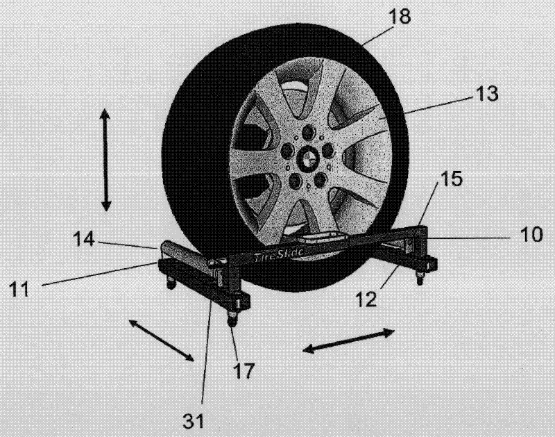
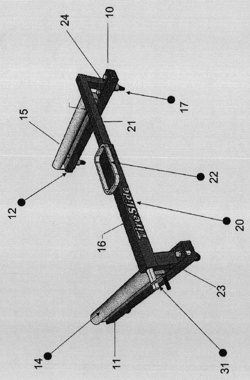
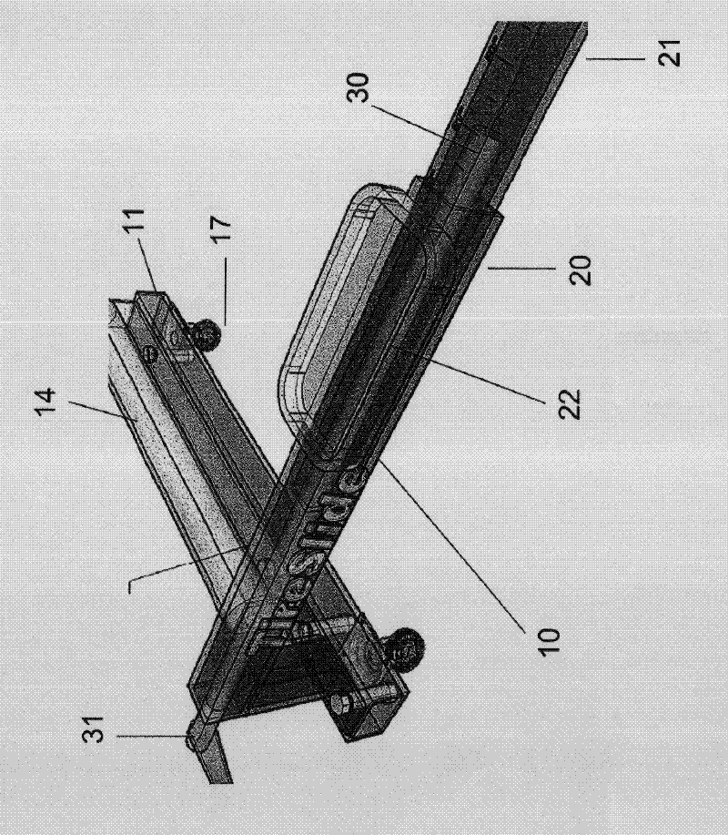
[0014] Such as figure 1 As shown, the tire changing device of the present invention is generally indicated by the reference numeral 10 and includes combined first and second spaced substantially parallel support members 11 and 12, each of which is made of a strong material such as metal or aluminum, which Strong enough to bear the weight of a vehicle tire 18 and a rim 13 mounted thereon. The support elements 11 and 12 are provided with wheels 17 for easy transport of the tire changing device 10 and positioning it relative to the hub of the vehicle. The support elements 11 and 12 also have roller elements 14 and 15 positioned and connected on the upper surface of said support elements 11 and 12 and extending parallel to said support elements 11 and 12 .

[0015] Said support elements 11 and 12 are connected together in a vertical plane by an intermediate connecting element 16 so as to form a tire changing device 10 of overall substantially U-shaped configuration.

[0016] Suc...


PUM


Abstract

A tire changing device includes two generally parallel spaced apart support members connected together through an intermediate linking member, the support members also being provided with roller members for working in cooperation with the telescopic movement of interconnected members of the linking member for positioning a tire/rim combination for mounting/demounting on a vehicle wheel hub.

Description

technical field [0001] The present invention relates generally to apparatus for changing tires on automobiles and vans, and more particularly to said changing apparatus for doing this efficiently and quickly. Background technique [0002] The prior art generally includes means for accomplishing the end result described above. However, the devices known to the Applicant are generally cumbersome to use and more particularly inconvenient to achieve the desired end result. [0003] In order to replace a tire on a vehicle, the tire must be lifted off the hub as the nuts are removed from the bolts extending from the hub, and conversely, the replacement tire must be lifted to achieve this during installation of the tire on the hub Accurate positioning. Typically, the lifting and positioning has been done manually. In many cases, however, the tires are too heavy and / or difficult to maneuver to be changed efficiently and quickly by a single person. [0004] The closest prior art ...

Claims


Application Information

Patent Timeline
IPC IPC(8): B60B29/00
CPCB60B29/002Y10T29/53922
Inventor 克劳迪奥·西尔韦斯特里德韦恩·威廉·普里斯
Owner 克劳迪奥·西尔韦斯特里
Why Eureka
Try Eureka