
Method for detecting offset signal corresponding to transmission leakage signal

A technology of leakage signal and bias signal, applied in transmission monitoring, electrical components, transmission system, etc., can solve the problems of increasing detection time, needing detection time, etc., and achieve the effect of improving receiving sensitivity

Inactive Publication Date: 2011-08-24
NETHOM
View PDF3 Cites 0 Cited by
  • Summary
  • Abstract
  • Description
  • Claims
  • Application Information

AI Technical Summary

Problems solved by technology

However, in the case of detecting the bias signal by scanning the entire area of ​​the I / Q vector phase plane, there is a problem that much detection time is required due to the resolution
Another problem is that the resolution has to be increased to increase the bias level by detecting the bias vector exactly, which is a factor that geometrically increases the detection time

Method used


Image

  • Method for detecting offset signal corresponding to transmission leakage signal
  • Method for detecting offset signal corresponding to transmission leakage signal
  • Method for detecting offset signal corresponding to transmission leakage signal

Examples


Embodiment Construction

[0023] The following description is not intended to limit the invention to the form disclosed herein. Accordingly, variations and modifications equivalent to the following teachings and the skill and knowledge of the related art are within the scope of the present invention. The embodiments described herein will further serve to explain known modes of carrying out the invention, and to enable others skilled in the art to make changes in these embodiments or other embodiments and having a particular application or use of the invention. to use the present invention.

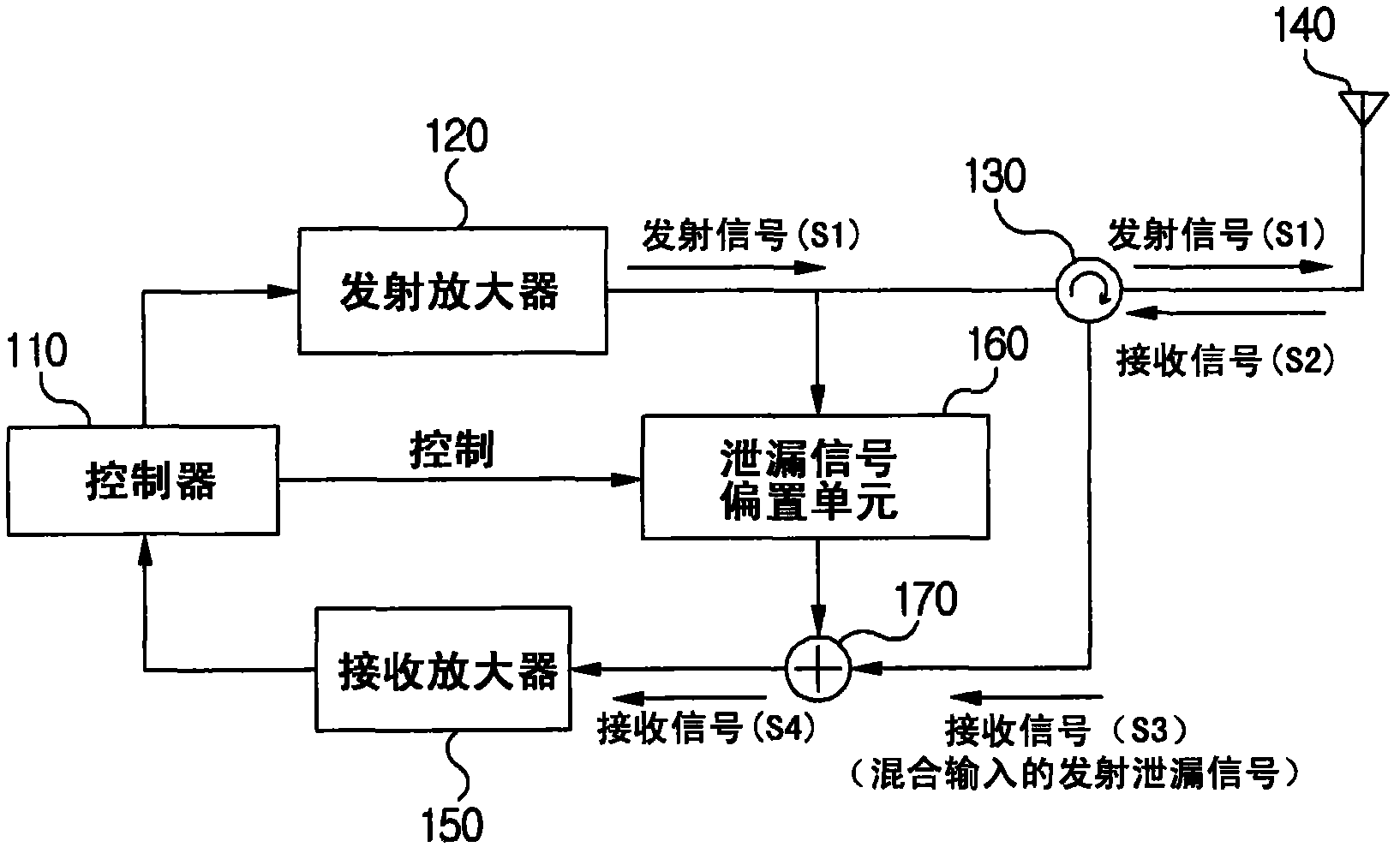
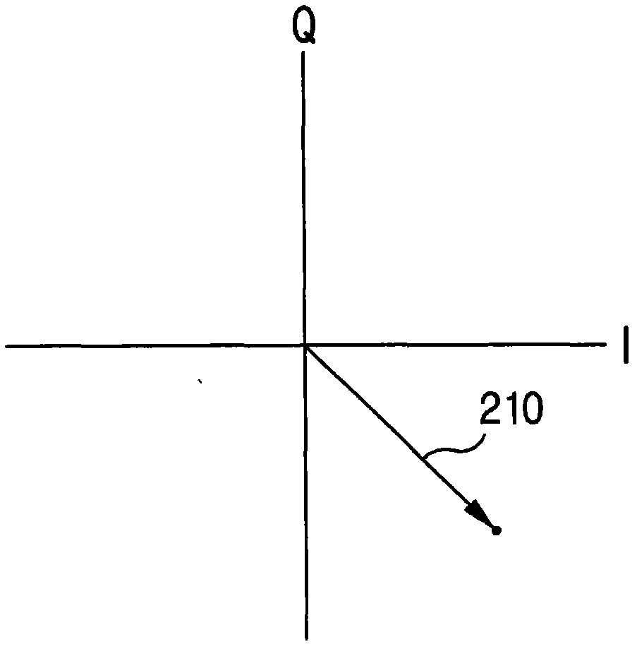
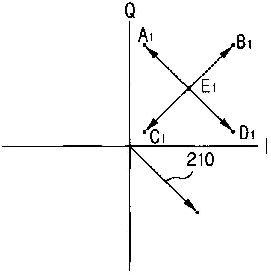
[0024] The embodiments disclosed herein and their advantages can be seen by referring to the accompanying drawings Figure 1-Figure 5 It is best understood that like numerals are used to refer to like or corresponding parts in the various drawings. Other features and advantages of the disclosed embodiments will become apparent to those of ordinary skill in the art upon examination of the following drawings and de...


PUM


Abstract

A method for detecting offset signal corresponding to transmission leakage signal is disclosed, whereby reception sensitivity can be improved by accurately offsetting a leakage signal in transmission signal mixedly inputted into the reception signal in a radio transceiver, and an offset signal corresponding to a transmission leakage signal can be rapidly detected in the radio transceiver to rapidly offset the transmission leakage signal included in a reception signal.

Description

technical field [0001] Teachings consistent with exemplary embodiments of the present invention relate to a method for detecting a bias signal corresponding to a transmit leakage signal, and more particularly to a method for detecting a bias signal corresponding to a transmit leakage signal employed in a radio transceiver system. Signal method. Background technique [0002] In the case of systems like RFID systems using the same transmit and receive frequencies, separation means are required to separate the transmit signal from the receive signal. For example, in RFID systems, readers use circulators or directional couplers to separate the transmitted signal from the received signal. In a general transceiver communication system, one antenna is used and different frequencies are used when transmitting and receiving signals. At this time, part of the transmission signal leaks and mixes with the reception signal. Therefore, in order to separate the transmission of a signal ...

Claims


Application Information

Patent Timeline
IPC IPC(8): H04B17/00H04B5/00
CPCH04B1/525
Inventor 崔宪洙
Owner NETHOM
Features
  • Generate Ideas
  • Intellectual Property
  • Life Sciences
  • Materials
  • Tech Scout
  • Unparalleled Data Quality
  • Higher Quality Content
  • 60% Fewer Hallucinations
Learn More