
Transmitting altimeter based on pseudo-code ranging and pseudo-code method

A radio altimeter and pseudo-code ranging technology, applied in the electronic field, can solve the problems of small size and weight of continuous wave altimeter, difficult to integrate and integrate, and large size of equipment, achieve high processing gain, avoid analog separation devices, Small size effect

Active Publication Date: 2008-08-13
SHAANXI CHANGLING ELECTRONICS TECH
View PDF0 Cites 43 Cited by
  • Summary
  • Abstract
  • Description
  • Claims
  • Application Information

AI Technical Summary

Problems solved by technology

The main advantage of this type of altimeter is that it adopts the continuous wave system. For a certain range of height measurement, the required transmission power is smaller than that of the pulse system altimeter. However, the disadvantage of this type of altimeter is that the range of height measurement is limited by the isolation of the antenna. The measurement accuracy is affected by the linearity and maximum frequency deviation of the voltage-controlled oscillator. To achieve high measurement accuracy, circuits such as linear calibration and frequency deviation control are required. Therefore, the continuous wave altimeter cannot be equipped with a small size and weight
[0005] At the same time, because the above two types of altimeters generally use analog working methods, there are many discrete components such as resistors, capacitors, transistors, and operational amplifiers, which not only cause the equipment itself to be large in size and heavy in weight, but also difficult to integrate with other systems.

Method used


Image

  • Transmitting altimeter based on pseudo-code ranging and pseudo-code method
  • Transmitting altimeter based on pseudo-code ranging and pseudo-code method
  • Transmitting altimeter based on pseudo-code ranging and pseudo-code method

Examples


Embodiment Construction

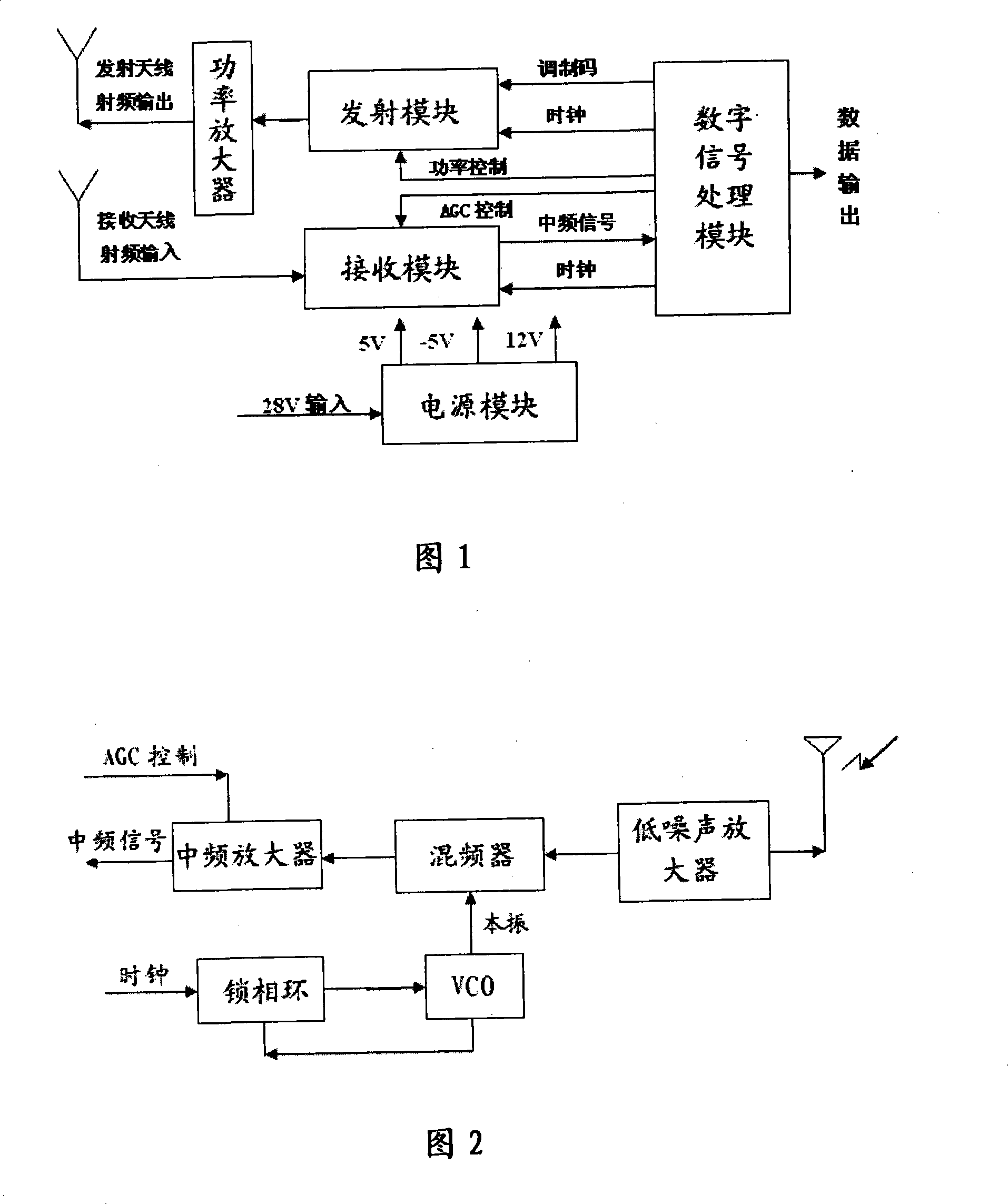
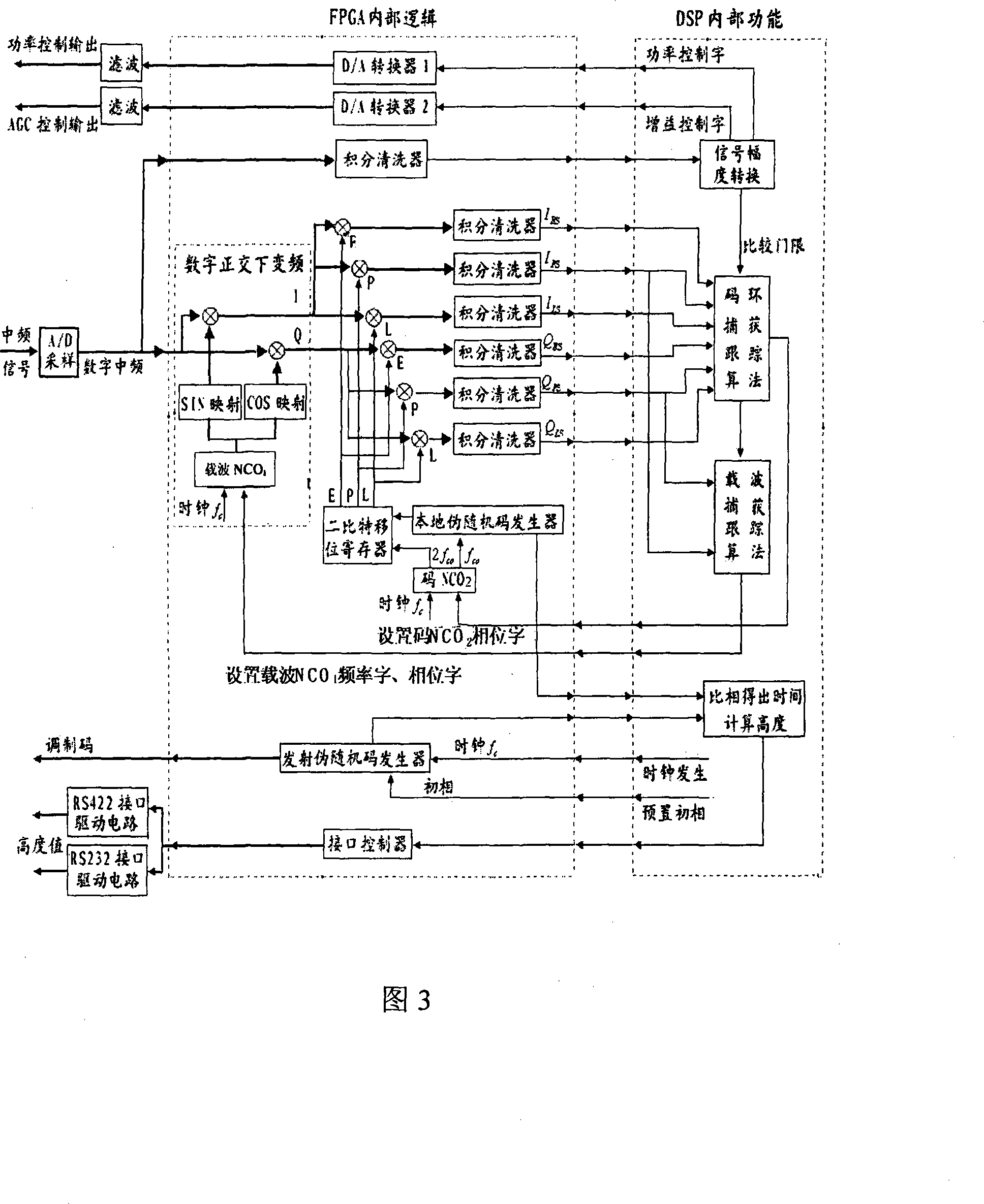
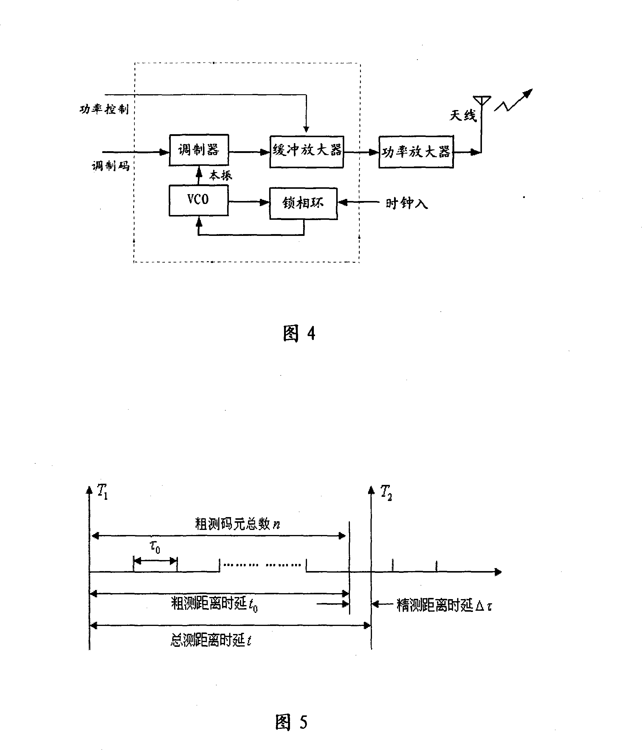
[0036] With reference to Fig. 1, the radio altimeter of the present invention is mainly made up of transmitting antenna, transmitting module, receiving antenna, receiving module, power amplifier, digital signal processing module, power supply module etc. The receiving antenna is connected to the input port of the receiving module through the feeder, and the output port of the receiving module is connected to the signal processing module; the transmitting antenna is connected to the output port of the power amplifier through the feeder, and the input port of the power amplifier is connected to the output port of the transmitting module , the modulation port of the transmitting module is connected with the modulation output port of the digital signal processing module, the clocks of the transmitting module and the receiving module are connected with the clock of the digital signal processing module, and each module is powered by the power supply module.

[0037] The working princ...


PUM


Abstract

The present invention discloses a radio altimeter based on PN code distance measurement which comprises of emitting module, receiving module and digital signal processing module, wherein, clock input signal of emitting module as intrinsic signal is transferred to modulator, after the intrinsic signal is modulated by modulating code input by digital signal processing module, variable RF signal is output as effect of power control signal, and radiated after amplified by power amplifier, the clock signal of receiving module as receiving intrinsic signal is mixed with receiving intrinsic, outputs intermediate frequency and transmitted to digital signal processing module after amplified of intermediate frequency amplifier as action of AGC control signal to produce PN code, clock, power control signal and AGC control signal, and capturing and tracking receiving signal to output measurement data. The present invention has merits of large height measurement range and high measurement precision, and is useful for measuring height of the flying load to ground.

Description

technical field [0001] The invention belongs to the field of electronic technology, and relates to electronic products, in particular to a radio altimeter, which can be used for the height of flight carriers such as airplanes from the ground. Background technique [0002] The current radio altimeter mainly has two systems, one is the pulse system, and the other is the FM continuous wave system. in: [0003] The pulse system altimeter uses a nanosecond high-voltage pulse to modulate a high-frequency oscillator to generate a high-power radio frequency pulse, which radiates to the ground through the transmitting antenna, and the echo signal reflected from the ground enters the receiver through the receiving antenna and passes through the receiver. After the internal mixer, amplifier, and detector, the delay of the transmitted pulse and the received pulse is compared to calculate the height relative to the ground. This system altimeter adopts the pulse working method, which ha...

Claims


Application Information

Patent Timeline
Patent Type & Authority Applications(China)
IPC IPC(8): G01S13/32G01S13/36
Inventor 范振林张宝会习睿波
Owner SHAANXI CHANGLING ELECTRONICS TECH
Learn More