First, problems of the receiving portion will be described.
As a second problem, when a
signal is received, a DC offset takes place, resulting in causing the reception characteristic of the portable telephone apparatus to deteriorate.
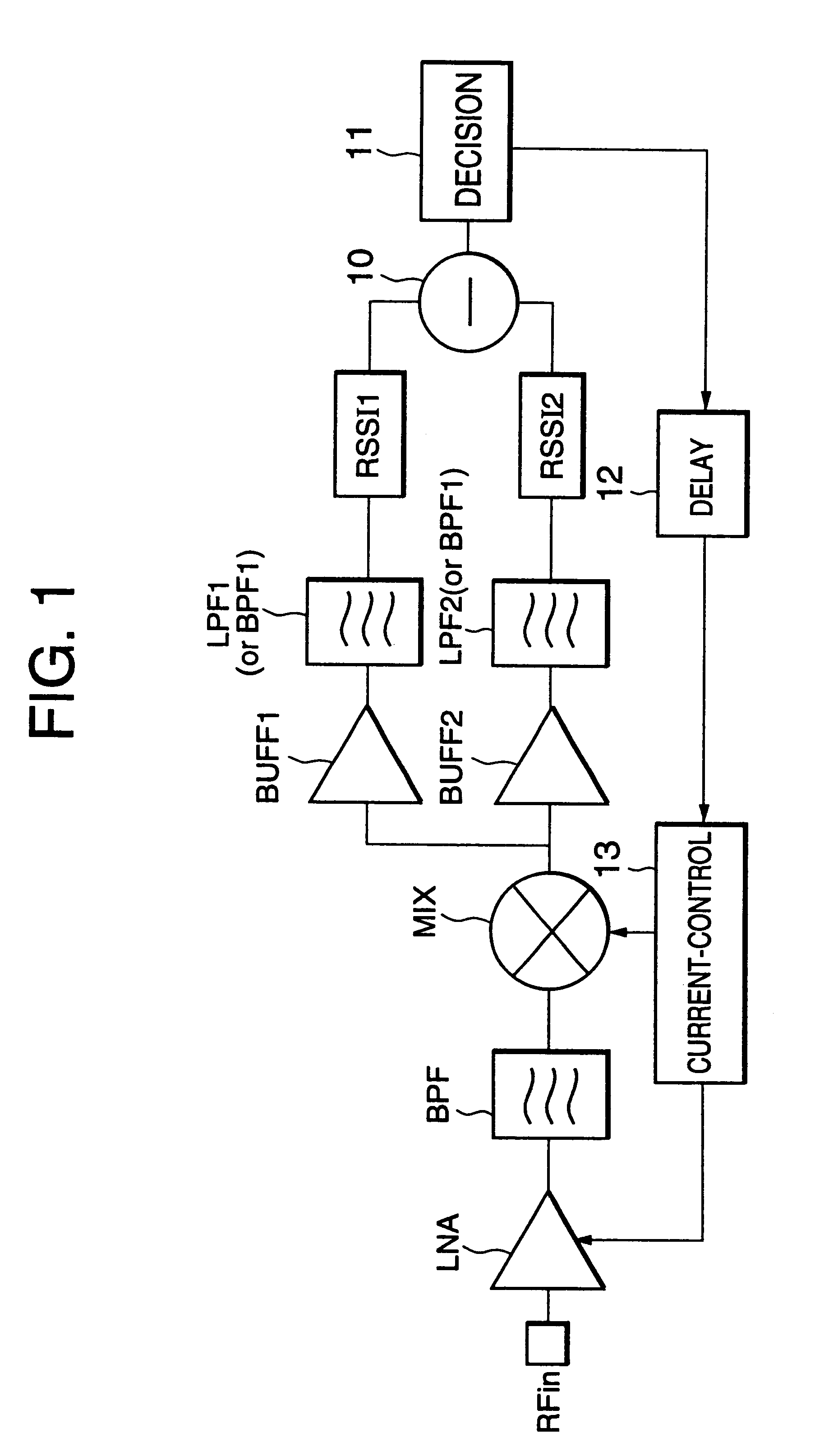
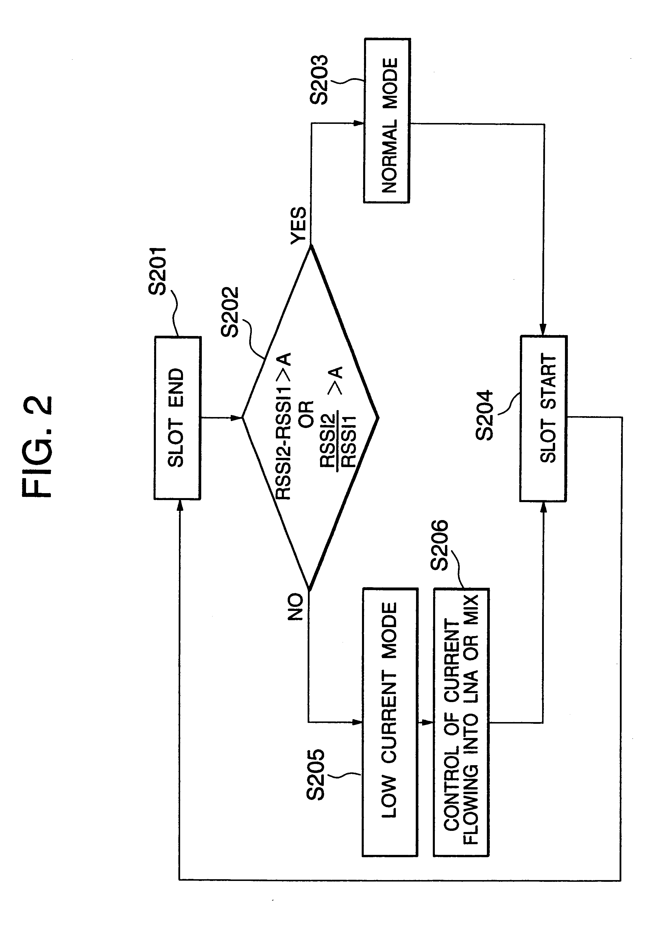
This problem relates to currents that flow in circuit blocks of the receiving portion (such as a
low noise amplifier and a frequency converter).
Thus, the power consumption of the portable telephone apparatus considered for the worst
radio wave environment excessively increases.
Next, the second problem of the receiving portion (namely, when a
signal is received, a DC offset causes the reception characteristic to deteriorate.
However, in an FSK
signal and a four-value FSK signal that have been used for high speed
data transmission in recent years and that have low modulation indexes, since there are many signal components in the vicinity of the DC region, the second problem cannot be practically solved.
Such a DC offset that takes place in the receiving portion has a problem in the
heterodyne system.
This problem is much serious in the direct conversion
system that has been used in the mobile communication field in recent years.
However, since a mixer used in the direct conversion type portable telephone apparatus does not have an infinite isolation, a local signal of the portable telephone apparatus is radiated from the antenna.
Since the DC offset varies depending on the amount of reflection of the local signal (namely, a reflector in the vicinity of the antenna), this DC offset more adversely affects the reception characteristic than a DC offset of the portable telephone apparatus and a DC offset of an active device.
Since the DC offset cannot be suppressed, the reception sensitivity deteriorates.
Thus, the conventional receiving portion cannot solve the two problems with respect to the low
current consumption and the improvement of the reception characteristic.
In particular, the problems in the direct conversion
system are severer than the problems in the
heterodyne system.
Thus, when the conventional
frequency synthesizer is used for a TDMA type portable telephone apparatus, the apparatus cannot search a blank channel using a blank slot in the communicating state.
However, since it is difficult to structure the
band pass filter and the directional coupler as an IC device, these parts should be mounted on a mother board.
Thus, unlike with the requirement of the
size reduction, the volume of the portable telephone apparatus adversely increases.
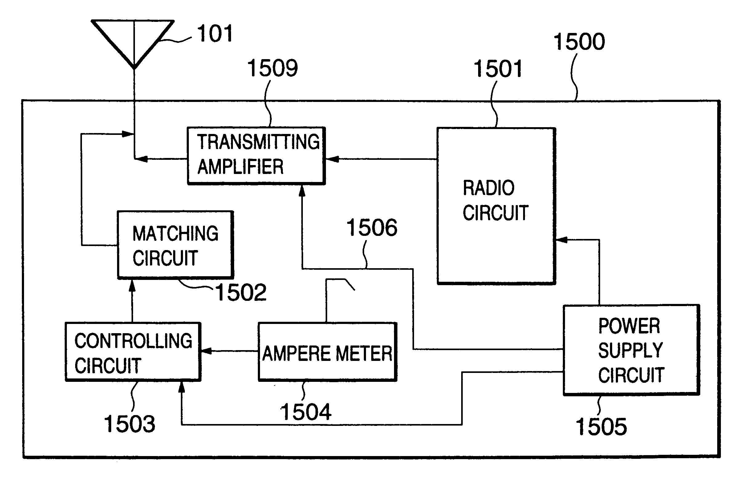
Consequently, the power consumption of the transmitting portion increases.
However, the size of the circuit of the portable telephone apparatus has not been sufficiently decreased.
On the other hand, there are problems of the body of the user against the antenna.
Thus, the body of the user causes the
radiation characteristic of the antenna to deteriorate.
Since the size and thickness of the portable telephone apparatus have been decreased, the ear of the user tend to further approach to the antenna, resulting in causing the antenna characteristic to further deteriorate.
As one of factors of such a deterioration, the body of the user causes the impedance of the antenna to fluctuate.
Thus, the technique for widening the
frequency band of the antenna contradicts with the decrease of the size of the portable telephone apparatus.
However, it cannot be said that this technique is not unconditionally good.
This is because the portable telephone apparatus is not always used in the state that the body of the user approaches the portable telephone apparatus.
When the amount of fluctuation varies, it is very difficult to optimally adjust the impedance of the antenna.
Thus, even if the impedance is optimized in the state that the body of the user approaches the antenna, the optimized antenna may be not optimum for other people.
Thus, the performance of the antenna deviates person by person.
Although this technique can be accomplished with a simple structure, it cannot deal with the variation of the size of ears of each user.
This probe may cause a
reflection loss, a conductor loss, and / or a loss of an RF signal to take place.
Thus, the current consumption is excessive large.
In addition, there is a time-varying DC offset that is caused by a reflection of an external reflector and that cannot be removed by an AC
coupling capacitor.
Thus, the deterioration of the reception sensitivity cannot be suppressed.
In addition, the synthesizer cannot search a blank channel with a blank channel slot in the communicating state.
Thus, the size of the portable telephone apparatus cannot be further decreased.
In the antenna, when the user who carries the portable telephone apparatus approaches the antenna, the antenna characteristic deteriorates.

