Centering device and centering method

A technology of centering device and eccentricity, which is used in positioning device, clamping, supporting and other directions to achieve the effect of saving space, improving durability and realizing correction accuracy

Inactive Publication Date: 2014-06-18
NTN CORP
View PDF7 Cites 0 Cited by
  • Summary
  • Abstract
  • Description
  • Claims
  • Application Information

AI Technical Summary

Problems solved by technology

Therefore, it is difficult to attach a gauge for measuring the amount of eccentricity to such a member with high precision.

Method used


Image

  • Centering device and centering method
  • Centering device and centering method
  • Centering device and centering method

Examples


Embodiment Construction

[0043] based on the following Figure 1 to Figure 16 Embodiments of the present invention will be described.

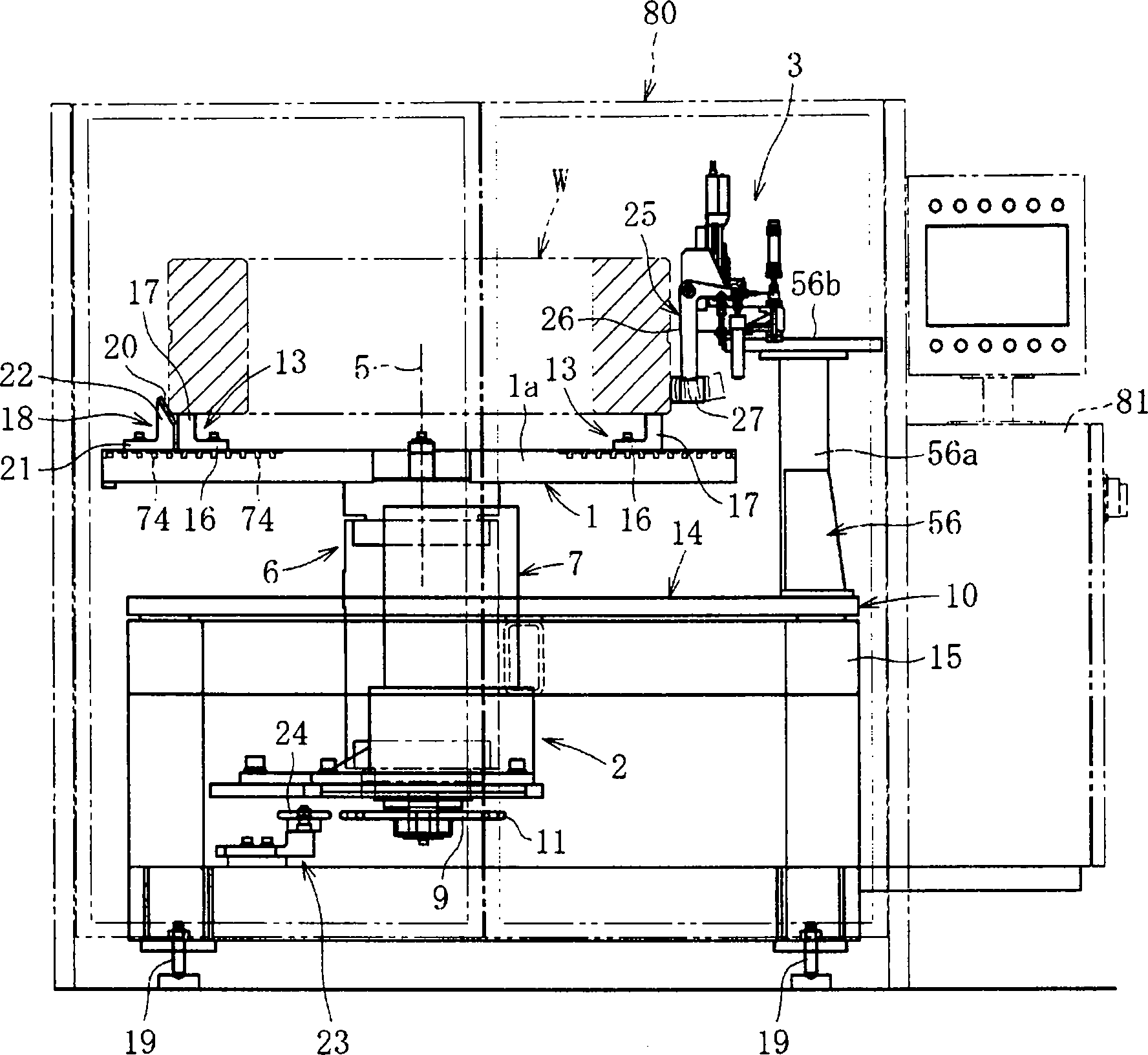
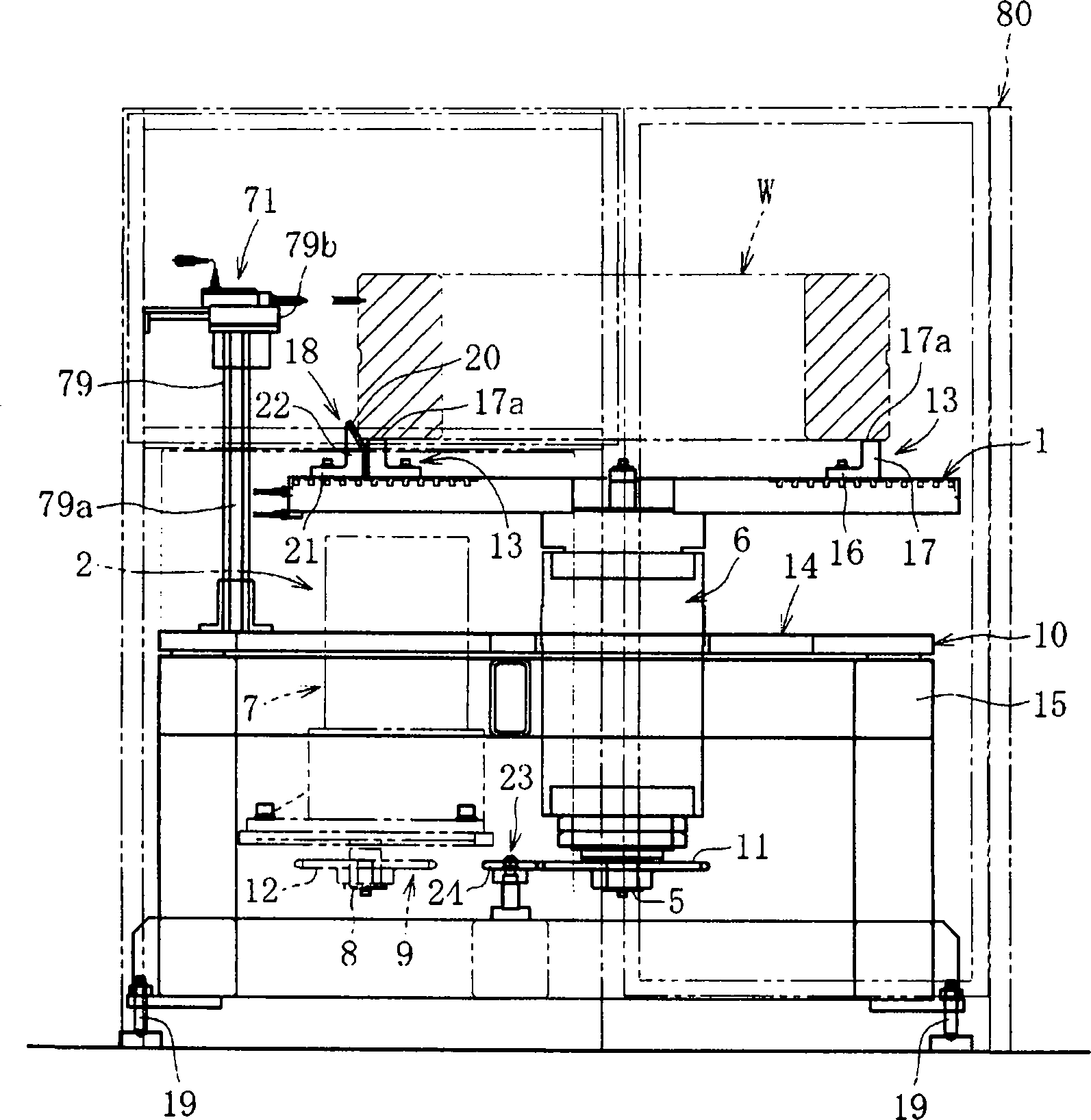
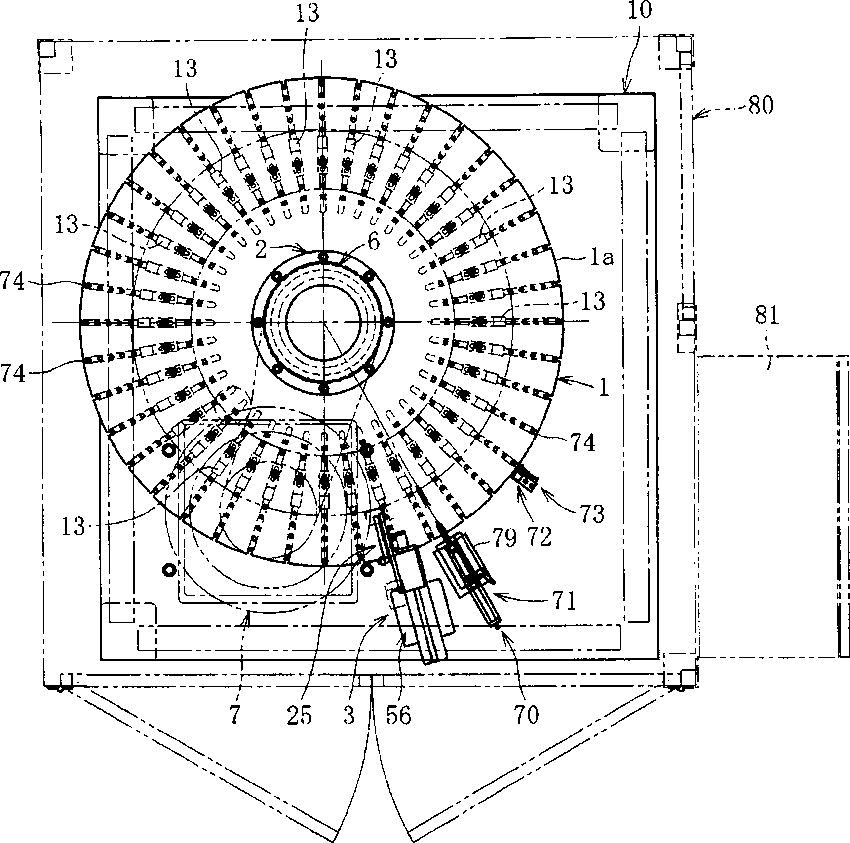
[0044] Figure 1 ~ Figure 3 The centering device of the present invention is shown. The centering device includes: a rotary table 1 on which a workpiece W is placed; a drive unit 2 for rotating the rotary table 1 around its axis; Inner ring or outer ring, etc.) The impact force imparting structure 3 that imparts impact force.

[0045] The drive unit 2 includes: a bearing structure 6 that supports the center shaft 5 of the turntable 1 so as to be rotatable about its axis, a drive motor 7 , an output shaft 8 of the drive motor 7 and the center shaft 5 Linkage members 9 linked together. The interlocking member 9 includes: a sprocket 11 mounted on the central shaft 5 of the turntable 1; a sprocket 12 mounted on the output shaft 8 of the driving motor 7; and a chain wound around the sprockets 11, 12. (Illustration omitted). The bearing structure 6 and the driving moto...


PUM


Abstract

Provided are a centering device and a centering method which enable simplification of the entire device and are capable of stably performing centering on a work. The centering method includes: detecting an eccentric amount of a work (W) which rotates through intermediation of a rotary table (1); performing, with an impact force imparted by hammer means (25) onto the work (W), a centering operation for correcting the eccentric amount; and repeating the centering operation until the eccentric amount reaches a preset target-convergence value.

Description

technical field [0001] The invention relates to a centering device and a centering method. Background technique [0002] When manufacturing an annular structure (ring-shaped workpiece) such as an inner ring or an outer ring of a bearing, a turning process or a grinding process is performed on the ring-shaped workpiece. In addition, in such a process, it is necessary to center the ring-shaped workpiece (workpiece) by a centering device. [0003] At present, when grinding a ring-shaped workpiece such as a large bearing, the workpiece is temporarily set on the grinding machine, and a skilled operator places a gauge for measuring eccentricity on the outer periphery of the workpiece, and the workpiece While rotating, the deviation during one rotation is measured. Then, predetermined centering is carried out by tapping with a hammer near the maximum position of the deviation. That is, in the manual centering work performed by such workers, skilled workers measure the eccentrici...

Claims


Application Information

Patent Timeline
Patent Type & Authority Patents(China)
IPC IPC(8): B23Q3/18B23Q17/22
CPCB23Q3/183B23Q17/2291B23Q3/00B23Q3/18B23Q17/22
Inventor 原田晴久名仓元治
Owner NTN CORP
Why Eureka
Try Eureka