
LED drive circuit

A technology of light-emitting diodes and driving circuits, which is applied in the layout of electric lamp circuits, light sources, electric light sources, etc., can solve the problem of high cost

Inactive Publication Date: 2011-08-31
马丽娟
View PDF2 Cites 1 Cited by
  • Summary
  • Abstract
  • Description
  • Claims
  • Application Information

AI Technical Summary

Problems solved by technology

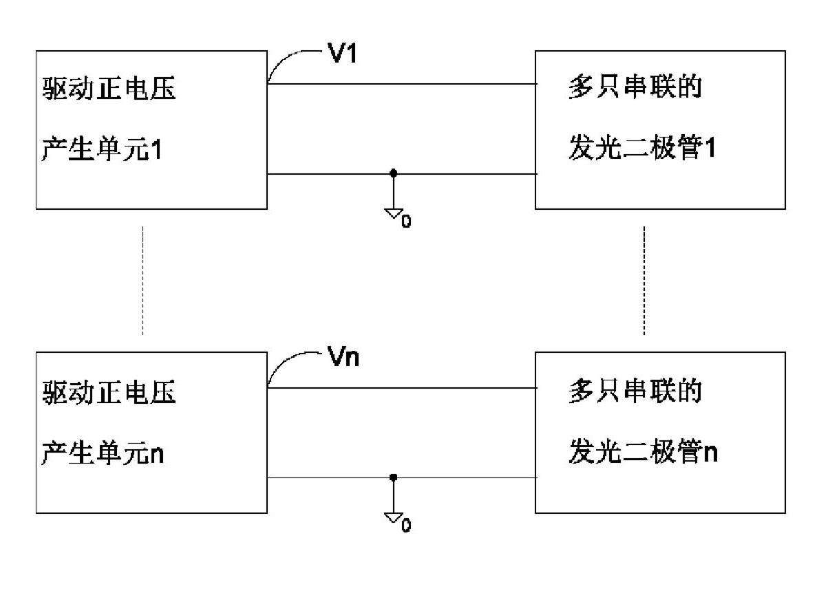
[0003] In many applications, it is necessary to use multiple light-emitting diodes to emit light at the same time. In order to achieve the purpose of having the same characteristics of light-emitting diodes, each light-emitting diode LED is required to have an equal working current. The existing technology uses light-emitting diodes in series to achieve the purpose of equal current. Use a unidirectional positive voltage to drive the light-emitting diode. This method has a simple structure, but in order to limit the absolute value of the voltage of the light-emitting diode LED to the reference zero point of the circuit from not exceeding the set value, it is necessary to use multiple driving positive voltage generating units. That is, there is a disadvantage of high cost

Method used


Image

  • LED drive circuit
  • LED drive circuit
  • LED drive circuit

Examples


Embodiment Construction

[0014] Some typical embodiments embodying the features and advantages of the present invention will be described in detail in the description in the following paragraphs. It should be understood that the invention is capable of various changes in different applications without departing from the scope of the invention, and that the description and drawings therein are illustrative in nature and not intended to limit the invention.

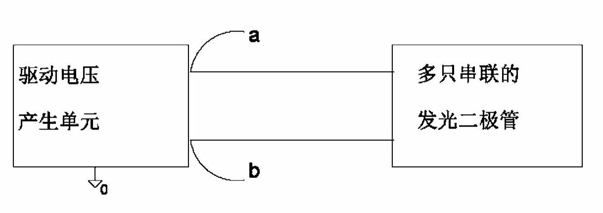
[0015] The present invention is a light-emitting diode driving circuit. The driving voltage generation unit simultaneously outputs positive voltage and negative voltage, and provides working voltages with opposite polarities to multiple light-emitting diodes connected in series. figure 2 is a block diagram of a light emitting diode driving circuit according to an embodiment of the present invention, figure 2 It includes: a driving voltage generating unit and a plurality of light-emitting diodes connected in series.

[0016] The above-mentioned d...


PUM


Abstract

The invention mainly aims to provide an LED (light emitting diode) drive circuit capable of reducing cost. To realize this objective, a driving voltage generation unit adopted by the invention can simultaneously output both positive voltage and negative voltage. With such voltages having opposite polarities to drive multiple series-wound LEDs, the magnitude of voltage of the LED to circuit reference zero point can be reduced, and meanwhile, the equality of working current of the LED can be ensured. The circuit comprises a driving voltage generation unit and multiple LEDs. The cathode of the series-wound LEDs is connected with a negative output terminal of the driving voltage generation unit while the anode of the series-wound LEDs is connected with a positive output terminal of the driving voltage generation unit.

Description

technical field [0001] The invention relates to a light emitting diode driving circuit and method. Background technique [0002] Light Emitting Diode (LED). [0003] In many applications, it is necessary to use multiple light-emitting diodes to emit light at the same time. In order to achieve the purpose of having the same characteristics of light-emitting diodes, each light-emitting diode LED is required to have an equal working current. The existing technology uses light-emitting diodes in series to achieve the purpose of equal current. Use a unidirectional positive voltage to drive the light-emitting diode. This method has a simple structure, but in order to limit the absolute value of the voltage of the light-emitting diode LED to the reference zero point of the circuit from not exceeding the set value, it is necessary to use multiple driving positive voltage generating units. That is, there is a disadvantage of high cost. refer to figure 1 . Contents of the inventi...

Claims


Application Information

Patent Timeline
IPC IPC(8): H05B37/02
Inventor 马丽娟
Owner 马丽娟
Learn More