Pneumatic linear driven chip picking and turning device

A technology of linear drive and flipping device, applied in electrical components, transportation and packaging, furnaces, etc., can solve the problems of difficulty, complex structure, and difficulty in ensuring rotation accuracy during flipping, and achieve the effect of safe chip pickup and high flipping accuracy.

Active Publication Date: 2013-03-27
HUAZHONG UNIV OF SCI & TECH
View PDF2 Cites 0 Cited by
  • Summary
  • Abstract
  • Description
  • Claims
  • Application Information

AI Technical Summary

Problems solved by technology

[0003] Among the existing chip picking and turning devices, the turret-type multi-picking head turning device provided by the patent CN 1613146A has the advantages of high work efficiency, but its own structure is relatively complicated, and it has high requirements for machining and control.
Because the device described in patent CN200920229522.3 is driven by a synchronous belt, it is difficult to ensure the rotation accuracy when turning over, especially when it needs a long delay to stop when it is fast rotating, it cannot meet the high-efficiency requirements; in addition, because the device does not have a linear motion drive Degree of freedom, it is more difficult to adjust the suction height and ensure the safety gap between the suction nozzle and the wafer chip
In the existing equipment, there is also a simple structural form of a rotating motor plus an operating arm. The operating arm rotates under the drive of the motor to complete the flipping of the chip, but the solution is rigid contact or non-contact during the chip suction process, which is easy to cause chip damage or pick up. Efficiency reduction and other issues

Method used


Image

  • Pneumatic linear driven chip picking and turning device
  • Pneumatic linear driven chip picking and turning device
  • Pneumatic linear driven chip picking and turning device

Examples


Embodiment Construction

[0018] The present invention is described now in conjunction with the preferred implementation examples of the accompanying drawings.

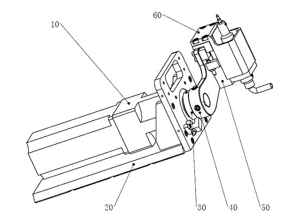
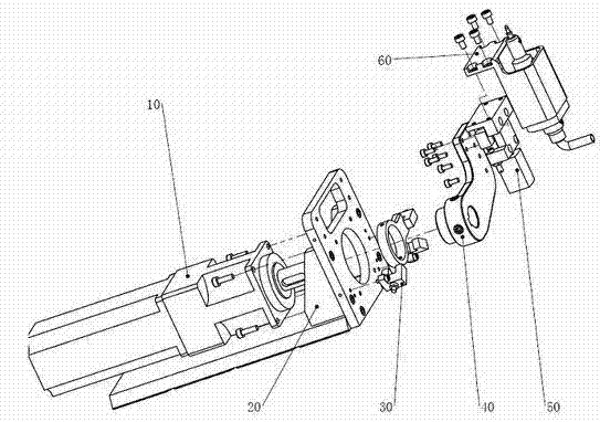
[0019] see figure 1 and figure 2 , The preferred embodiment of the present invention mainly includes a rotary drive assembly 10 , a support assembly 20 , a sensor assembly 30 , a turning arm assembly 40 , a linear drive assembly 50 , and a chip suction assembly 60 . The support assembly 20 can install and fix the entire device in the chip flip-chip bonding equipment, and the rotation assembly 10 drives the flip arm assembly 40, the linear drive assembly 50 and the chip suction assembly 60 to rotate to provide power for flip chips. The linear drive assembly 50 pushes the chip pick-up assembly 60 to achieve linear motion, and can complete the gap between the suction nozzle and the wafer chip by fine-tuning the stroke, so as to ensure effective pick-up of the chip. The chip pick-up component 60 includes an elastic element, which has the functi...


PUM


Abstract

The invention provides a pneumatic linear driven chip picking and turning device which mainly comprises a rotary driving assembly, a turning arm assembly, a linear driving assembly, a chip adsorbing assembly and a sensor assembly. Under the drive of the rotary driving assembly, the chip absorbing assembly is driven to turn by the turning arm assembly, thus a chip can be turned, the adsorbing nozzle of the adsorbing assembly is driven by the linear driving assembly to get close to or far away from the chip, the chip can be adsorbed and picked safely, and the sensor assembly is used for detecting the turning angle of the adsorbing assembly and providing the turning angle to an external control system. The rotary driving assembly adopts the manner of matching a servo motor with a speed reducer, thereby ensuring higher turning precision; and the linear driving assembly adopts the pneumatic driving manner to adjust the distance between the adsorbing nozzle and the chip, thereby ensuring the safe clearance between the adsorbing nozzle and the chip.

Description

technical field [0001] The invention relates to the field of semiconductor packaging, in particular to a chip picking and flipping device. Background technique [0002] With the wide demand and gradual upgrading of semiconductor packaging equipment, flip-chip (flip-chip) technology has been promoted and applied more rapidly, making flip-chip packaging technology products can be applied to the RFID field with fewer pins and thousands of chips at the same time. pins in the field of IC memory device packaging. The main advantages of flip chip technology are: (1) the device itself is small and does not require the surrounding space of wire bonding; (2) after its operation is completed, it can realize a shorter signal path and have better electrical performance; (3) ) For multi-pin operation process, the efficiency is higher than that of wire bonding. With the wide application of flip chip technology, the chip pick-up and flip device with the function of picking up and flipping...

Claims


Application Information

Patent Timeline
Patent Type & Authority Patents(China)
IPC IPC(8): H01L21/00B65G49/07B65G47/91H01L21/683
Inventor 尹周平陈建魁熊有伦黄永安
Owner HUAZHONG UNIV OF SCI & TECH
Why Eureka
Try Eureka