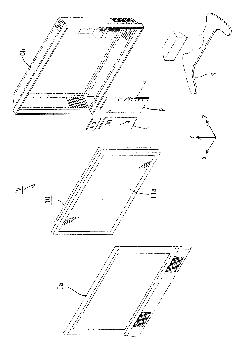
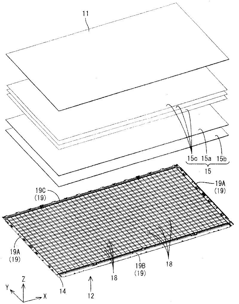
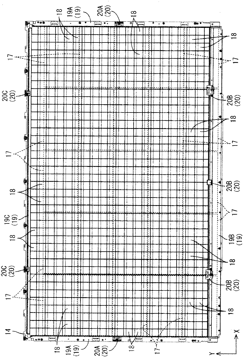
Illuminating device, display device and television receiver

A technology for lighting devices and display devices, which is applied in the field of display devices, television receiving devices, and lighting devices, and can solve problems such as uneven brightness of the light exit surface, easy warping in the direction of separation from the substrate, uneven brightness of the display surface, etc. , to achieve the effect of eliminating uneven brightness

Inactive Publication Date: 2011-09-07
SHARP KK
View PDF6 Cites 6 Cited by
  • Summary
  • Abstract
  • Description
  • Claims
  • Application Information

AI Technical Summary

Problems solved by technology

[0005] However, when the front end side of the light guide body is separated from the base material, in the case where an external force acts on the light guide body, the front end side of the light guide body Tends to warp in the direction of separation from the substrate
In this way, when the light guide is warped (wobbled), the incident position of the light from the light emitting element is deviated, so that brightness unevenness occurs on the light exit surface.
Therefore, brightness unevenness tends to occur on the display surface of the liquid crystal panel.

Method used


Image

  • Illuminating device, display device and television receiver
  • Illuminating device, display device and television receiver
  • Illuminating device, display device and television receiver

Examples


Embodiment approach 2

[0135] Next, use Figure 15 Embodiment 2 of the present invention will be described. In this embodiment, the plate spring 47 in the first embodiment is changed to a coil spring 49, and the structure of the concave portion 48 is partially changed, and the same reference numerals are attached to the common structures, and the structure, function, and effect repeated in the first embodiment are described below. Its description is omitted.

[0136] The coil spring 49 has a well-known structure in which a metal wire is wound into a cylinder. A general-purpose coil spring can be used as such a coil spring 49 . On the other hand, the recessed portion 50 for accommodating the coil spring 49 is shorter in depth from the rear end of the substrate mounting portion 30 than the recessed portion 48 of the first embodiment. Both end portions of the coil spring 49 are accommodated in a pair of spring receiving portions 17 d and 50A formed inside the concave portion 50 . On the upper surfa...

Embodiment approach 3

[0138] Next, use Figure 16 Embodiment 3 of the present invention will be described. In the present embodiment, the leaf spring 47 in the first embodiment is replaced with a sponge material 51 , and the same reference numerals are assigned to common structures, and descriptions of structures, operations, and effects that overlap with those in the first embodiment are omitted.

[0139] The sponge material 51 is a flexible resin material, and is made of, for example, a synthetic resin material such as polyurethane form or a rubber material such as rubber sponge. When such a sponge material 51 is used, it is only necessary to sandwich the sponge material 51 between the upper surface 17 c of the LED board 17 and the inner wall upper surface 52A constituting the recess 52 . Therefore, the installation of the sponge material 51 is easy. In addition, since the sponge material 51 is deformed to fit the shape of the recessed portion 52 in which the sponge material 51 is accommodated, ...


PUM


Abstract

The invention provides an illuminating device, a display device and a television receiver. Provided is a backlight device (12), which has a light guide plate (18) and an LED (16) extending in a front-rear direction, and has a rear end side of the light guide plate (18) fixed to the LED substrate (17) in a state where a front end side of the light guide plate (18) is separated from the LED substrate (17). The backlight device is provided with a light outputting section (31), which is arranged on a front end side of the light guide plate (18) and has a light outputting surface (36) for outputting light emitted from the LED (16) to an optical member (15); a substrate attaching section (30), which is arranged on the rear end side of the light guide plate (18) and is attached to the LED substrate (17); a clip (23) which fixes the LED substrate (17) and the substrate attaching section (30) to each other; and a plate spring (47) which urges a rear portion and the LED substrate (17) in a direction of separating the rear portion and the LED substrate by means of a clip (23) on the substrate attaching section (30).

Description

technical field [0001] The present invention relates to an illuminating device, a display device and a television receiving device. Background technique [0002] As an illuminating device used in a display device such as a television receiver, for example, an illuminating device described in Patent Document 1 below is known. This illuminating device includes: a light emitting element as a light source; and a light guide that emits light incident inside from the light emitting element to an optical member. The light guide is in a form extending in the front-rear direction. A light exit portion having a light exit surface from which the light is emitted is formed at a front end portion of the light guide. A mounting portion to which the light guide is mounted is formed at a rear end portion of the light guide. The light guide is fixed to the substrate by fixing the attachment portion and the base with the fixing member. In this fixed state, the front end side of the light ...

Claims


Application Information

Patent Timeline
Patent Type & Authority Applications(China)
IPC IPC(8): F21S2/00G02F1/1333H04N5/645H04N5/66F21Y101/02
CPCG02F1/133606G02B6/0046G02B6/0088G02F1/133608G02B6/0055G02B6/0021G02B6/008
Inventor 笠井信宏
Owner SHARP KK
Why Eureka
Try Eureka