Engraving device, cassette member and method for forming engraving pattern

A pattern and component technology, applied in the field of engraving devices, can solve problems such as inability to engrave and deterioration of engraving quality, and achieve the effect of preventing damage

Inactive Publication Date: 2011-09-14
SEIKO PRECISION CO LTD
View PDF1 Cites 0 Cited by
  • Summary
  • Abstract
  • Description
  • Claims
  • Application Information

AI Technical Summary

Problems solved by technology

If the marking action becomes unstable, it will cause the deterioration of the marking quality or the marking will not be possible.

Method used


Image

  • Engraving device, cassette member and method for forming engraving pattern
  • Engraving device, cassette member and method for forming engraving pattern
  • Engraving device, cassette member and method for forming engraving pattern

Examples


Embodiment Construction

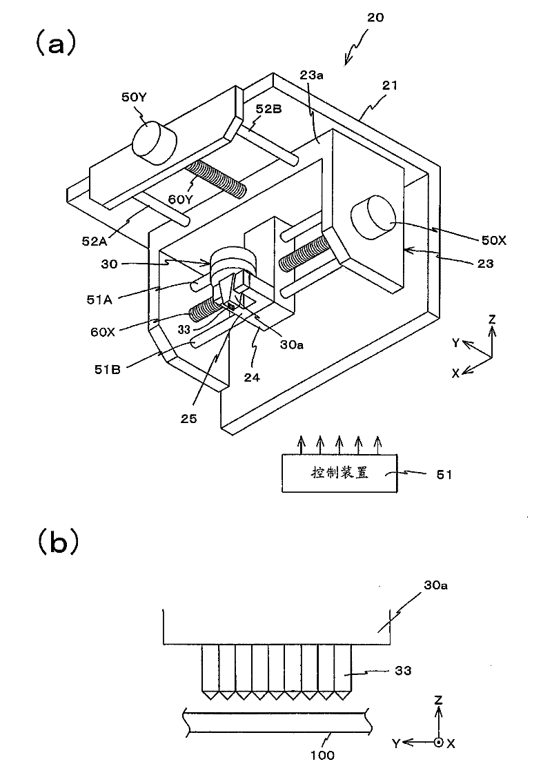
[0051] Hereinafter, a marking device according to an embodiment of the present invention will be described with reference to the drawings.

[0052] The marking device according to this embodiment forms a two-dimensional code, characters, and the like composed of a plurality of dots on the surface of an object to be marked.

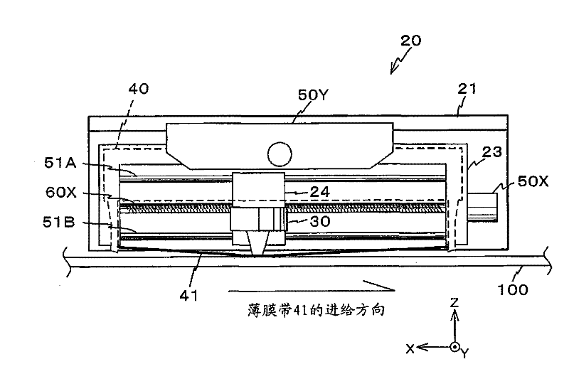
[0053] The marking device 20 according to this embodiment is as figure 1 (a) includes as shown: Y moving body 23; X moving body 24 supported on Y moving body 23; U-shaped bracket 25 fixed on X moving body 24; Striking head 30. In addition, the marking device 20 further includes a control device 51 that controls the overall operation.

[0054] The engraving device 20 moves the engraving head 30 in the X-axis direction and the Y-axis direction by means of the Y moving body 23 and the X moving body 24. Engraving multiple points to form a variety of engraving patterns.

[0055] The Y moving body 23 is composed of a member having a U-shaped cross section, ...


PUM


Abstract

The engraving device (20) comprises a plurality of engraving needles (33), an engraving head (30) for engraving patterns on an object to be engraved (100) by utilizing the engraving needles (33) and a support part for supporting slices before the engraving head (30). The engraving head (30) engraves the object to be engraved (100) separated by the slices supported by the support part by utilizing the engraving needles (33). A film belt (41) is arranged between the front end of the engraving needles (33) and the object to be engraved (100).

Description

technical field [0001] The present invention relates to an engraving device, a cartridge member, and a method for forming an engraved pattern. Background technique [0002] In recent years, in order to improve the management of products and the ability of tracking service, the engraving device that uses a plurality of engraving pins to engrave on the surface of objects to be engraved such as industrial products attracts attention (for example, refer to Japanese Patent Application Laid-Open Publication No. 08-276607 ). This marking device directly draws or marks a two-dimensional code or various characters on the surface of the target object by touching the tip of the stylus to the target object to mark (form) a plurality of dots. [0003] Such as Figure 5 As shown, in this marking device, the marking needle 33 is biased upward (in the +Z direction) by the return spring (coil spring) 113 , and its +Z side end abuts against the drive lever 114 . A movable yoke 116 is fixed ...

Claims


Application Information

Patent Timeline
Patent Type & Authority Applications(China)
IPC IPC(8): B44B3/02
Inventor 宍户满春
Owner SEIKO PRECISION CO LTD
Why Eureka
Try Eureka