Gear shift prompting equipment and method

A technology of equipment and gears, applied in the direction of mechanical equipment, components with teeth, belts/chains/gears, etc., can solve the problem of low gear accuracy, low fuel economy, and no consideration of various specific conditions of the vehicle, etc. problem, to achieve the effect of simple structure and reduced fuel consumption

Active Publication Date: 2011-09-14
WEICHAI POWER CO LTD
5 Cites 38 Cited by

AI-Extracted Technical Summary

Problems solved by technology

[0003] However, these existing methods do not consider various specific conditions of the vehicle during driving, such as real-time engine speed, torque, engine universal characteristic curve, external characteristic curve, optimal operating point curve and other vehicle...

Abstract

The invention discloses gear shift prompting equipment and a gear shift prompting method. The gear shift prompting equipment comprises an information collecting device which is used for collecting running information of a vehicle, an optimal rotation speed determining device which is connected with the information collecting device and is used for determining the optimal rotation speed of an engine according to the running information of the vehicle, an optimal gear determining device which is connected with the optimal rotation speed determining device and is used for determining the optimal gear of a gearbox of the vehicle on the basis of the optimal rotation speed, and a prompting device which is connected with the optimal gear determining device and is used for prompting a user to shift to the optimal gear.

Application Domain

Technology Topic

Image

  • Gear shift prompting equipment and method
  • Gear shift prompting equipment and method
  • Gear shift prompting equipment and method

Examples

  • Experimental program(1)

Example Embodiment

[0029] The present invention will be explained and illustrated in more detail below in conjunction with the drawings. It should be understood that the drawings and embodiments of the present invention are only used for exemplary purposes and are not used to limit the protection scope of the present invention.
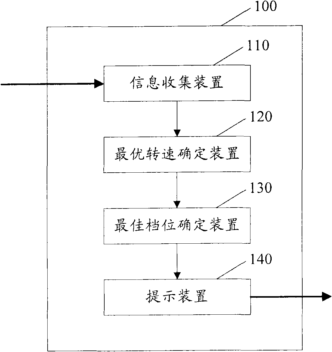
[0030] figure 1 It is a schematic block diagram of a gear shift prompt device 100 according to an embodiment of the present invention. figure 1 The gear shift prompt device 100 shown may include: an information collection device 110, an optimal rotation speed determination device 120, an optimal gear determination device 130, and a prompt device 140.
[0031] The information collection device 110 may be configured to collect vehicle operation information. In an embodiment, the information collection device 110 may include: a device for acquiring one or more of the following: transmission output shaft speed, engine speed, torque, vehicle speed, engine universal characteristic curve, external characteristic curve , Best operating point curve.
[0032] The optimal rotation speed determining device 120 may be connected to the information collecting device 110, and may be configured to determine the optimal rotation speed of the engine according to vehicle operation information.
[0033] In one embodiment, the optimal rotation speed determining device 120 may include: a device for calculating the current power of the engine; and a device for obtaining the optimal rotation speed according to the current power according to the universal characteristic curve of the engine.
[0034] In another embodiment, the optimal rotation speed determining device 120 may include: a device for calculating the current power of the engine according to vehicle operation information; a device for calculating the ratio of the current torque of the engine to the maximum possible torque at the current rotation speed; When the ratio is greater than or equal to a predetermined threshold, the current engine speed is determined as the optimal speed; and when the ratio is less than the predetermined threshold, the engine's updated torque is determined according to the engine's external characteristic curve and based on the engine's current power And update torque to obtain the optimal engine speed, wherein the ratio of the update torque to the maximum possible torque is greater than or equal to a predetermined threshold.
[0035] In another embodiment, the optimal rotation speed determining device 120 may include: a device for obtaining the acceleration of the vehicle; a device for comparing the acceleration with an acceleration threshold; a device for calculating the current power of the engine; A device for determining the ratio of the current torque to the maximum possible torque at the current speed; a device for determining the current engine speed as the optimal speed when the ratio is greater than or equal to a predetermined threshold; and a device for determining the engine speed as the optimal speed when the ratio is less than the predetermined threshold A device that determines the updated torque of the engine and obtains the optimal speed of the engine according to the current power and the updated torque of the engine, wherein the ratio of the updated torque to the maximum possible torque is greater than or equal to a predetermined threshold.
[0036] The optimal gear determining device 130 may be connected to the optimal rotational speed determining device 120, and may be configured to determine the optimal gear of the transmission of the vehicle based on the optimal rotational speed. In one embodiment, the optimal gear determination device 130 may include: a calculation device configured to calculate the ratio of the optimal rotation speed to the rotation speed of the gearbox output shaft; and the search device is configured to configure according to the transmission gear ratio constant Table, searching for the set of candidate gear positions of the gearbox according to the ratio; the obtaining device is configured to obtain the set of candidate speeds of the engine from the set of candidate gear positions of the gearbox according to the transmission gear ratio constant configuration table; the selecting device is configured To select a rotation speed from the candidate rotation speed set according to the best operating point curve of the engine; and the determining device is configured to determine a gear position corresponding to the selected rotation speed in the candidate gear position set as the best gear position.
[0037] In an embodiment, the selection device of the optimal gear determining device 130 may include:
[0038] A device for determining the candidate rotation speed closest to the best operating point curve of the engine in the candidate rotation speed set; and a device for selecting the determined candidate rotation speed from the candidate rotation speed set.
[0039] The prompting device 140 may be connected to the optimal gear determining device 130 and may be configured to prompt the user of the optimal gear. In one embodiment, the prompting device 140 may include a device for preferentially displaying the best gear in the information display.
[0040] It should be understood that the above-mentioned various devices of the present invention can be implemented by a combination of existing hardware, firmware, software, and machines. For example, each of the above-mentioned devices can be implemented using commonly used or future application specific integrated circuits, special digital processors, programmable logic controllers (such as field programmable gate array FPGAs, etc.) and so on.
[0041] figure 2 It is a flowchart of a gear shift prompt method according to an embodiment of the present invention. figure 2 The shift prompt method shown can be used figure 1 The gear shift shown prompts the device to complete.
[0042] In step 201, vehicle operation information is collected.
[0043] This step can be figure 1 The shown information collection device 110 of the gear shift prompt device 100 can also be completed by any other suitable equipment that can be thought of by those skilled in the art. In step 201, for example, vehicle operation information such as the transmission output shaft speed, engine speed, torque, vehicle speed, universal characteristic curve of the engine, external characteristic curve, and optimal operating point curve of the vehicle can be collected.
[0044] In step 202, the optimal engine speed is determined according to the vehicle operation information.
[0045] This step can be figure 1 The optimal rotation speed determining device 120 of the gear shift prompting device 100 shown is completed, and it can also be completed by any other suitable device that can be thought of by those skilled in the art.
[0046] In an embodiment, the current power of the engine may be calculated first according to the vehicle operating information, and then the optimal speed is obtained according to the current power according to the universal characteristic curve of the engine, thereby completing step 202.
[0047] The universal characteristic curve of the engine usually refers to the engine speed as the abscissa, the average effective pressure or torque as the ordinate, and the load characteristic curve, speed characteristic curve, power and fuel consumption and other parameters of the diesel engine at each speed are integrated and drawn. Curve. From the universal characteristic curve, the torque, fuel consumption rate and other parameters of the diesel engine at different power states at each specific speed can be read. From the universal characteristic curve, the best economic operation area of ​​the diesel engine can be observed. The universal characteristic curve of the engine can be stored in the ECU in advance, for example. The vehicle operation information may include, for example, the speed of the gearbox output shaft, the engine speed, the torque, the vehicle speed, the universal characteristic curve of the engine, the external characteristic curve, and the optimal operating point curve. The current power of the engine can be obtained, for example, by multiplying the engine speed and torque. After obtaining the current power of the engine, the optimal engine speed can be obtained by querying the optimal operating point curve in the universal characteristic curve. Figure 4 The best operating point curve of the engine is schematically shown. For example, when the best operating point curve is the curve when the engine has the best fuel economy, you can query the curve to get the optimal speed when the engine has the best fuel economy; when the best operating point curve is the engine with the best fuel economy When the curve is at the best power performance, the optimal speed when the engine has the best power performance can be obtained by querying the curve.
[0048] In the second embodiment, step 202 can be completed by the following process: first calculate the current power of the engine according to the vehicle operating information; then calculate the ratio of the current torque of the engine to the maximum possible torque at the current speed; when the ratio is greater than or equal to a predetermined When the threshold is set, the current engine speed is determined as the optimal speed; and, when the ratio is less than the predetermined threshold, the engine's updated torque is determined according to the engine's external characteristic curve, and the engine's optimal speed is obtained according to the engine's current power and updated torque , Where the ratio of the updated torque to the maximum possible torque is greater than or equal to a predetermined threshold. The following will combine image 3 This embodiment is described in detail. The external characteristic curve of the engine usually refers to the characteristic curve of the engine speed measured when the engine emits the maximum power under the best working condition of the engine.
[0049] In the third embodiment, step 202 can be completed by the following process: first obtain the acceleration of the vehicle; compare the obtained acceleration with a preset acceleration threshold, if the acceleration is greater than the acceleration threshold, the remaining processing is the same as the second The embodiment is similar: for example, the current power of the engine can be calculated, the ratio of the current torque of the engine to the maximum possible torque at the current speed can be calculated, when the ratio is greater than or equal to a predetermined threshold, the current speed of the engine is determined as the optimal speed, and when the ratio is less than When the threshold is predetermined, the updated torque of the engine is determined according to the external characteristic curve of the engine, and the optimal engine speed is obtained according to the current power and the updated torque of the engine, wherein the ratio of the updated torque to the maximum possible torque is greater than or equal to the predetermined threshold.
[0050] In step 203, based on the optimal speed, the optimal gear of the vehicle's transmission is determined.
[0051] This step can be figure 1 The optimal gear determining device 130 of the gear shift prompting device 100 shown is completed, and it can also be completed by any other suitable equipment that can be thought of by those skilled in the art.
[0052] In one embodiment, the ratio of the optimal speed to the speed of the gearbox output shaft can be calculated first; according to the gearbox gear ratio constant configuration table, the gearbox candidate gear set is searched according to the ratio; according to the gearbox gear ratio Constant configuration table, get the set of candidate speeds of the engine from the set of candidate gears of the gearbox; select a speed from the set of candidate speeds according to the best operating point curve of the engine; and combine the set of candidate gears with the selected The gear position corresponding to the rotation speed is determined as the best gear position, and step 203 is completed.
[0053] In another embodiment, in addition to performing the steps of the foregoing embodiment, the process of implementing step 203 can also be used in the process of selecting a rotation speed from the set of candidate rotation speeds according to the best operating point curve of the engine, first determining the candidate rotation speed The candidate rotational speeds that are closest to the best operating point curve of the engine in the set are then selected from the candidate rotational speed set. The following will combine image 3 This embodiment is described in detail.
[0054] In step 204, the user is prompted with the best gear.
[0055] This step can be figure 1 The shown prompting device 140 of the gear shift prompting device 100 can also be completed by any other suitable equipment that can be thought of by those skilled in the art.
[0056] In step 204, for example, the best gear can be displayed in the information display first, so that the user can quickly know which gear is the best gear of the current vehicle, so that the user can change gears, thereby saving fuel and reducing fuel consumption. Fuel consumption. The information display can have various forms. For example, the information display can be: LCD, VFD, OLED, etc., and for example, the information display can be a flat display or a head-up display.
[0057] then, figure 2 The process ends.
[0058] image 3 It is a flowchart of a shift prompt method according to another embodiment of the present invention. image 3 The illustrated embodiment is a specific implementation of the shift prompt method of the present invention, and those skilled in the art should fully understand image 3 The embodiments of the present invention are only exemplary rather than restrictive. The shift prompt method and device of the present invention are not limited to the specific examples given in this specification, but may include those skilled in the art according to the present invention. Any implementation that comes to mind.
[0059] In step 301, collect vehicle operation information.
[0060] As mentioned above, the vehicle operation information in the present invention may include, for example, the gearbox output shaft speed, engine speed, torque, vehicle speed, engine universal characteristic curve, external characteristic curve, optimal operating point curve and other information.
[0061] In step 302, the current power of the engine is calculated according to the vehicle operating information.
[0062] According to the vehicle operation information obtained in step 301, the current engine speed and current torque can be obtained, so that the current engine power can be obtained by multiplying the current engine speed and the current torque. Those skilled in the art can also obtain the current power of the engine according to other known technical means commonly used in the art, and are not limited to the specific implementation disclosed in the present invention.
[0063] In this embodiment, the current torque of the engine is denoted as M C , And record the current speed as n C , The current output power of the engine can be obtained as:
[0064] P C =M C ×n C (1)
[0065] In step 303, the torque ratio of the current torque of the engine to the maximum possible torque at the current speed is calculated.
[0066] Torque generally refers to the amount of force the engine drives the drive shaft to rotate. Generally, under the condition of fixed power, torque is inversely proportional to engine speed. The faster the speed, the smaller the torque, and the slower the speed, the greater the torque.
[0067] The maximum possible torque at the current speed can be obtained, for example, according to the universal characteristic curve of the engine. In this embodiment, the maximum possible torque of the engine at the current speed is recorded as M Cmax , And mark the ratio of the current torque of the engine to the maximum possible torque at the current speed as R M ,then
[0068] R M =M C /M Cmax (2)
[0069] In step 304, it is determined whether the torque ratio obtained from step 303 is less than a predetermined threshold.
[0070] The predetermined threshold value for the ratio can be obtained in various ways, for example, it can be pre-designated according to empirical values, obtained according to current technology, calculated according to a mathematical model, or suitably pre-set values ​​that can be realized by those skilled in the art.
[0071] In one embodiment, the predetermined threshold may be 60%, for example. At this time, the ratio R obtained from step 303 M Compare with a predetermined threshold, if the ratio R M Less than the predetermined threshold, go to step 305; if the ratio R M If it is not less than (that is, greater than or equal to) the predetermined threshold, proceed to step 306.
[0072] In step 305, the updated torque of the engine is determined according to the external characteristic curve of the engine, and the optimal engine speed is obtained according to the current power and the updated torque of the engine.
[0073] When the torque ratio R obtained from step 303 M When it is less than the predetermined threshold, enter this step from step 304, which means that the current engine load rate is low and the engine speed needs to be reduced. According to the engine's external characteristic curve, an updated torque (denoted as M) can be obtained, where the ratio of the updated torque to the maximum possible torque at the current speed R M It is greater than the predetermined threshold in step 304. The external characteristic curve of the engine can be further obtained by reading the CAN bus to obtain the engine configuration information. Figure 4 The external characteristic curve of the engine is schematically shown.
[0074] According to the current engine power P obtained in step 302 C And update the torque M, the optimal speed (denoted as n) can be obtained as follows:
[0075] n=P C /M (3)
[0076] In step 306, the current engine speed is determined as the optimal engine speed.
[0077] In step 307, the rotation speed ratio between the optimal rotation speed and the transmission output shaft rotation speed is calculated.
[0078] In an example, the ratio between the optimal speed and the speed of the output shaft of the gearbox can be denoted as i, where i=n/n o , N o Is the speed of the gearbox output shaft, which can be obtained from vehicle operating information, for example.
[0079] In step 308, according to the gear ratio constant configuration table of the gearbox, the set of candidate gear positions of the gearbox is searched according to the speed ratio obtained in step 307.
[0080] The gearbox gear ratio constant configuration table can be obtained, for example, from the configuration information and document description when the vehicle leaves the factory. It describes the ratio of the input speed (and engine speed) of the vehicle gearbox to the output speed and the ratio of each gear Correspondence. In an example, it is assumed that the gearbox of the vehicle has 5 gears, where the gear ratio of the highest gear (for example, the 5th gear) is 1:1, and the 4th to 1st gear is, for example, 1: 1.27, 1:1.27 2 , 1:1.27 3 , 1:1.27 4.
[0081] Assuming that the speed ratio obtained in step 307 is 1:1.2, then in step 308, it can be obtained that the gearbox gear ratios of the 4th and 5th gears are closer to the speed ratio of 1:1.2, so the 4th gear And the fifth gear is added to the candidate gear set as a member of the set.
[0082] In step 309, a set of candidate speeds of the engine is obtained from the set of candidate gears of the gearbox according to the gearbox gear ratio constant configuration table.
[0083] First, the candidate speeds corresponding to each candidate gear in the candidate gear set can be obtained according to the gearbox speed ratio constant configuration table, and then these candidate speeds can be regarded as members of the candidate speed set.
[0084] In step 310, a speed is selected from the candidate speed set according to the best operating point curve of the engine.
[0085] In this step, the candidate rotational speed that is closest to the best operating point curve of the engine in the candidate rotational speed set can be determined first, and then the candidate rotational speed that is closest to the candidate rotational speed set is selected from the candidate rotational speed set.
[0086] In step 311, the gear corresponding to the selected rotation speed in the candidate gear set is determined as the best gear.
[0087] Since the candidate gear set and the candidate speed set are in one-to-one correspondence according to the transmission gear ratio constant configuration table, according to the candidate speed selected from the candidate speed set in step 310, the candidate gear set can be determined Corresponding candidate gear position, and determine the candidate gear position as the best gear position.
[0088] In step 312, the user is prompted with the best gear position.
[0089] This step is similar to step 204 and will not be repeated here.
[0090] then, image 3 The process ends.
[0091] The gear shift prompting device and method of the present invention can be used in an engine control system, such as a national iii or higher control system. At present, all the national iii and above engine electronic control systems used by commercial vehicles (truck) in China have CAN bus information exchange function, and they all follow the SAE J1939 communication protocol regulations, so the present invention has a wider scope of application. The invention can communicate with the engine ECU, the combination instrument and the whole vehicle controller on the whole vehicle, and is used for the combination instrument information display and gear shift control.
[0092] The gear shift prompting device and method of the present invention can be used in vehicles with manual transmissions, and the gear shift prompting device and method of the present invention can prompt the driver in real time to the gearbox gear position of the best economical fuel under the current vehicle operating conditions. , Prompt the driver to change gears, so as to achieve the purpose of reducing fuel consumption. The gear shift prompting device of the present invention has a simple structure, and can be realized on the basis of the original vehicle without adding any sensors. In addition, the gear shift prompting device and method of the present invention can output standard transmission gear position CAN bus information for use by other electronic control units on the vehicle.
[0093] The present invention can be implemented in hardware, firmware, software, or a combination of software and hardware. The hardware can be implemented by an application specific integrated circuit or a programmable logic controller; the software part can be stored in a memory and executed by an appropriate instruction execution system, such as a microprocessor, a personal computer (PC) or a mainframe.
[0094] It should be noted that, in order to make the present invention easier to understand, the above description omits some more specific technical details that are well-known to those skilled in the art and may be necessary for the implementation of the present invention.
[0095] The purpose of the description of the present invention is provided for illustration and description, not for exhaustively enumerating or limiting the present invention to the disclosed form. Many modifications and changes are obvious to those of ordinary skill in the art.
[0096] Therefore, the selection and description of the embodiments are to better explain the principle of the present invention and its practical application, and to make those of ordinary skill in the art understand that all modifications and changes fall under the right without departing from the essence of the present invention. It is within the protection scope of the present invention as defined by the requirements.

PUM

no PUM

Description & Claims & Application Information

We can also present the details of the Description, Claims and Application information to help users get a comprehensive understanding of the technical details of the patent, such as background art, summary of invention, brief description of drawings, description of embodiments, and other original content. On the other hand, users can also determine the specific scope of protection of the technology through the list of claims; as well as understand the changes in the life cycle of the technology with the presentation of the patent timeline. Login to view more.

Similar technology patents

Mechanical flywheel for bowed rotor mitigation

ActiveUS20180283274A1Reduce fuel consumptionPower installationsElectric power distributionAcceleration ratePeak demand
Owner:THE BOEING CO

Engine-off power steering system

InactiveUS20080135325A1Reduce fuel consumptionSatisfactory control characteristicGas pressure propulsion mountingSpeed sensing governorsPower steeringHigh pressure
Owner:ENVIRONMENTAL PROTECTION AGENCY US

Slag soil transfer system

Owner:HYVA MECHANICS (CHINA) CO LTD

Classification and recommendation of technical efficacy words

  • Simple structure
  • Reduce fuel consumption

Microlithographic projection exposure apparatus

InactiveUS20050068499A1Simple structureReliable and low-maintenance operationProjectorsPhotomechanical exposure apparatusCamera lensPhysics
Owner:CARL ZEISS SMT GMBH

Gear train of automatic transmission for vehicles

InactiveUS20090280947A1Improving power delivery performanceReduce fuel consumptionToothed gearingsTransmission elementsVariatorEngineering
Owner:HYUNDAI MOTOR CO LTD +1
Why Eureka
Try Eureka