Flow restoration systems and methods for use

A material, obstructive technology, applied in the field of flow restoration system and use, can solve the problem of removing material, difficulty, etc.

Active Publication Date: 2011-09-14
ARROW INT INC
View PDF4 Cites 42 Cited by
  • Summary
  • Abstract
  • Description
  • Claims
  • Application Information

AI Technical Summary

Problems solved by technology

[0007] While this addresses the immediate goal of removing attached material from the vessel wall, it is often difficult to re

Method used


Image

  • Flow restoration systems and methods for use
  • Flow restoration systems and methods for use
  • Flow restoration systems and methods for use

Examples


Embodiment Construction

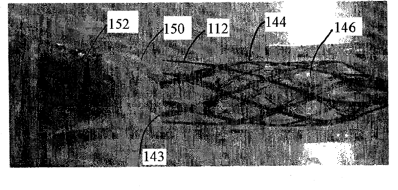
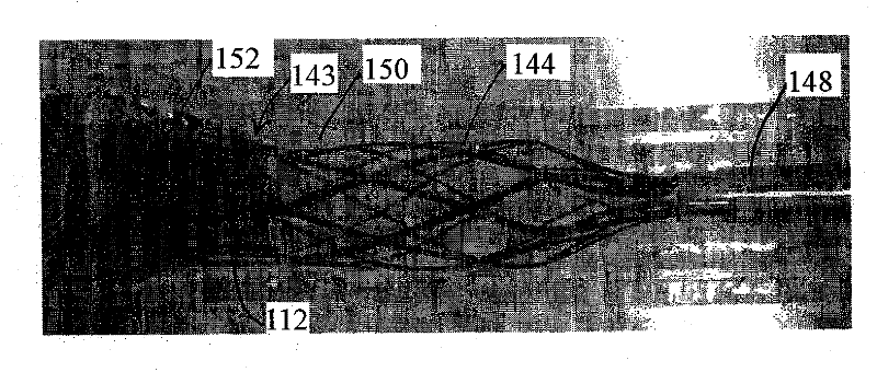
[0037] Go to attached image, figure 1 Illustrated is an exemplary embodiment of a device 10 for treating a body cavity, for example for removing thrombi, blood clots, objects, debris and / or or other undesirable or obstructive substances. Generally, the device 10 includes an external access cannula or other tubular member 20, and optionally an occlusion device 30 and a macerator device 40, which together can provide a flow restoration system, for example, to remove an obstruction from a body cavity of a patient's body. sexual substance. Additionally, such systems may include one or more additional components not shown, such as, for example, one or more guidewires, syringes or other sources of inflation medium and / or vacuum, and the like.

[0038] Cannula 20 may be an elongated tubular body (e.g., an introducer or a procedure cannula) including a proximal end (not shown), a distal end 22 sized to be introduced into a body lumen, and a A lumen 24 extends between the end and th...


PUM


Abstract

Apparatus and methods are provided for removing obstructive material within a body lumen. The apparatus includes a macerator device deployable from a sheath that includes an expandable cage carried by a shaft and within a constraint tube. The shaft is movable relative to the constraint tube for deploying and expanding the cage within a body lumen such that an open end of the cage is oriented towards obstructive material. The cage is advanced to capture the material or the material is directed into the cage using an expandable member expanded beyond the material and retracted to direct the material into the cage. The cage is withdrawn into the constraint tube to compress the cage radially inwardly. Material extending through apertures in the cage are sheared off by a sharpened edge of the constraint tube.; The smaller, sheared off particles are then aspirated from the body lumen through the sheath.

Description

[0001] related application [0002] This application claims co-pending U.S. Provisional Patent Application No. 61 / 099,171, filed September 22, 2008, U.S. Provisional Application No. 61 / 143,603, filed January 9, 2009, and Priority to US Provisional Patent Application No. 61 / 152,227, the entire disclosure of which is expressly incorporated herein by reference. technical field [0003] The present invention generally relates to treatment of obstructive material (e.g., thrombus, organ stenosis) and / or Device where no substance is desired. More particularly, the present invention relates to devices for removing or otherwise trapping thrombus or other obstructive material within body lumens, and methods of making and using such devices. Background technique [0004] Flow in blood vessels or other body lumens within a patient's vasculature may become narrowed or eventually interrupted for a variety of reasons. For example, inflammation and / or cell proliferation may lead to progr...

Claims


Application Information

Patent Timeline
IPC IPC(8): A61B17/22A61B17/50
CPCA61B2017/320741A61B2017/22079A61B17/320725A61B2017/22067A61B2017/2215A61B17/221A61B17/3207A61B2017/22069A61B2017/00867
Inventor 杰弗里·A·克罗里克胡安·多明戈达宇施·米尔扎伊詹姆士·H·德雷赫尔
Owner ARROW INT INC
Why Eureka
Try Eureka