Devices and methods for temporarily opening a blood vessel

a technology for temporarily opening and removing obstructions, applied in medical science, surgery, other medical devices, etc., can solve problems such as problems such as mechanical removal of obstructions, and achieve the effects of reducing the overall profile of the catheter, facilitating blood flow through the obstruction, and minimizing or eliminating tissue necrosis and severity of strok

a technology for temporarily opening and removing obstructions, applied in medical science, surgery, other medical devices, etc., can solve problems such as problems such as mechanical removal of obstructions, and achieve the effects of reducing the overall profile of the catheter, facilitating blood flow through the obstruction, and minimizing or eliminating tissue necrosis and severity of strok

US20100114135A1Inactive Publication Date: 2010-05-06STRYKER CORP

Image

  • Devices and methods for temporarily opening a blood vessel
  • Devices and methods for temporarily opening a blood vessel
  • Devices and methods for temporarily opening a blood vessel

Examples


Embodiment Construction

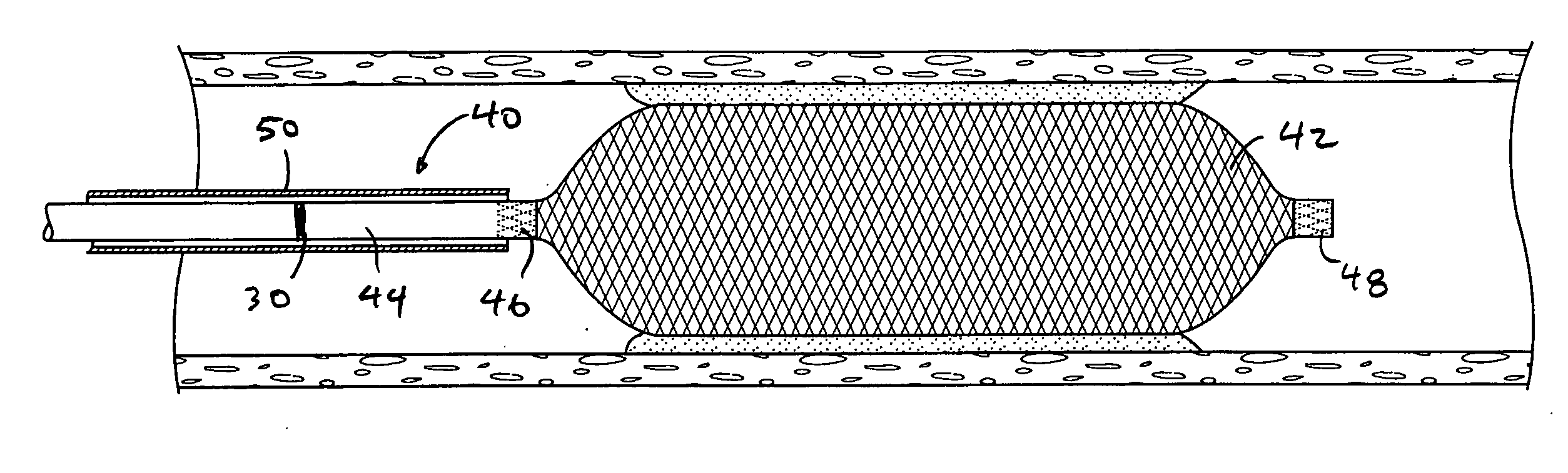
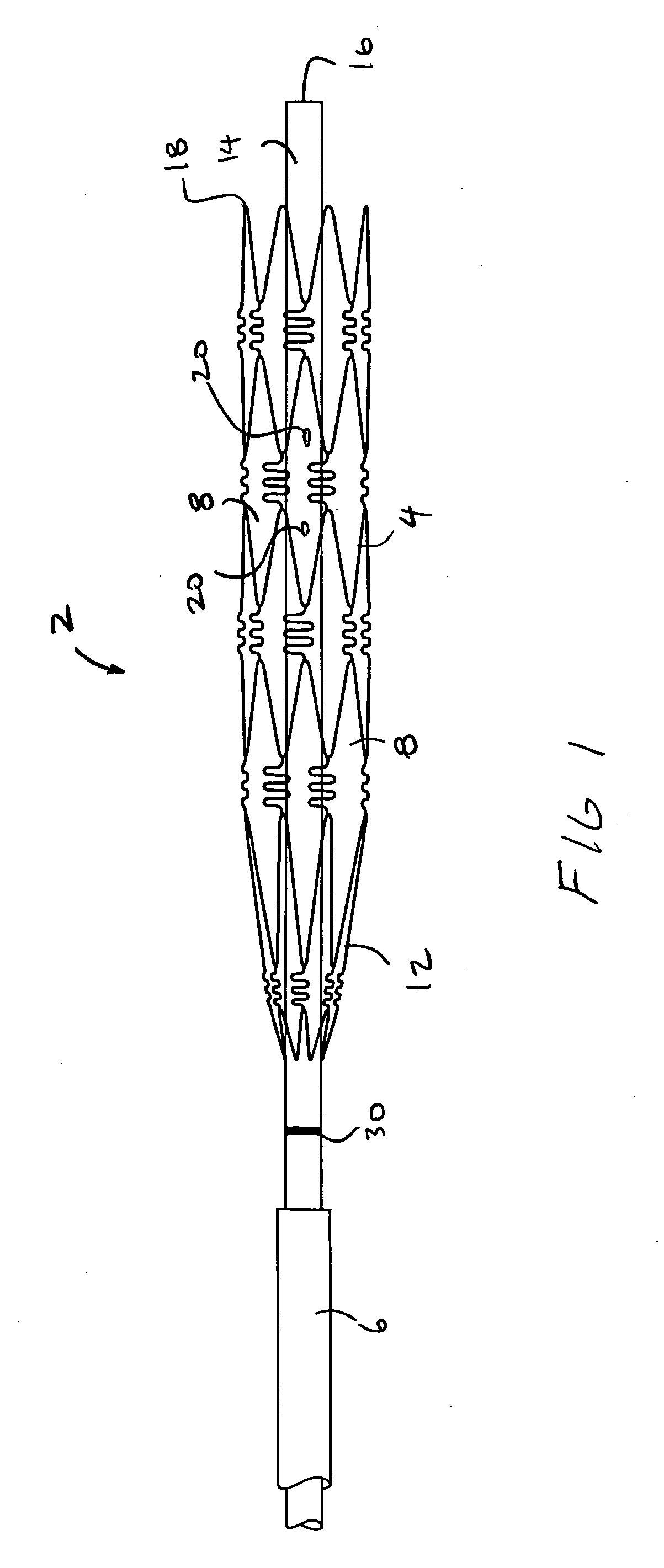
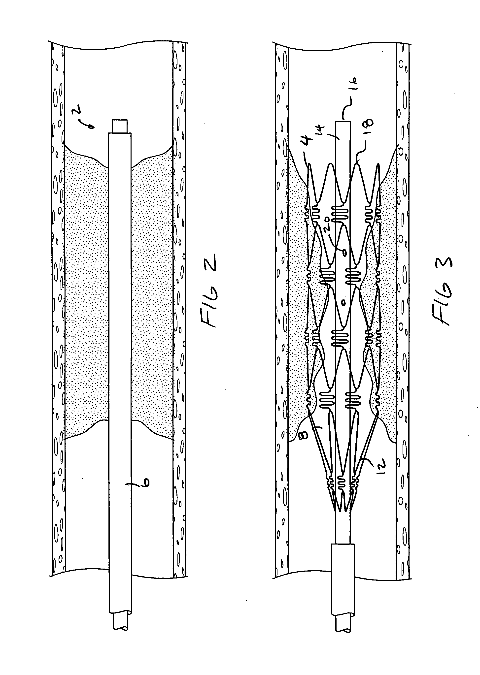
[0019]Referring to FIGS. 1-3, a device 2 for temporarily opening a blood vessel is shown. The device 2 includes an expandable cage 4. The cage 4 is naturally biased toward the expanded position of FIG. 1 but can be collapsed into a delivery catheter 6 as shown in FIG. 2. The cage 4 may also be expanded with a balloon or the like rather than being self-expandable without departing from various aspects of the present invention.

[0020]The cage 4 may be formed in a manner similar to a stent. As such, the cage 4 may be formed from a single integrally formed piece of material such as a stainless steel or nitinol tube with material removed from the tubes to form openings 8 in the cage 4. The cage 4 may also be formed in any other manner, which produces a relatively open structure for the reasons described below. The cage 4 has a relatively open structure so that the openings 8 in a proximal portion 12 of the cage 4 may permit blood or other fluids to pass therethrough.

[0021]The cage 4 is mo...


PUM


Abstract

A device for temporarily opening a blood vessel is provided. The device has an expandable cage mounted over a shaft having a lumen. The lumen has a distal end, which extends beyond the distal end of the cage so that the lumen provides access to the vasculature distal to the obstruction.

Description

BACKGROUND OF THE INVENTION[0001]The present invention is directed to devices and methods for temporarily opening a blood vessel. The present invention may be used to temporarily open a blood vessel in any part of the body such as in the cerebral vasculature.[0002]The present invention is also directed to opening blood vessels and may be useful in dissolving or removing obstructions from blood vessels as well. Mechanical removal of obstructions can be problematic at times due to the forces necessary to release the obstruction from the vessel wall. This could be a result of the obstruction physiologically binding to the vessel wall, increased blood pressure at the face of the clot, vessel collapse during retrieval and most likely some combination of any or all of these scenarios.SUMMARY OF THE INVENTION[0003]The present invention provides a cage, which is used to temporarily open a vessel. In one application, the cage may be used to open a vessel at a location where an obstruction ex...

Claims


Application Information

Patent Timeline
06 May 2010
Publication
US20100114135A1
IPC
A61B17/22; A61M25/04; A61M31/00; A61M29/00
CPC
A61B17/32056; A61B17/3207; A61B2017/00867; A61B2017/320733; A61F2/013; A61F2/91; A61F2/95; A61F2230/0054
Inventors
WILSON, SCOTT; PEDERSEN, KIRK